More from the Treenut woodpile ....
Building a Rolling Ball Clock out of scrap wood.
January 2018 - June 2018
- Some notes on Stepper Motors
- Link to web-based control page (simulated)
- January 2019 -- 2020: Building 2 More Rolling Ball Clocks
- May 2024: Clock display case construction
I've always wanted to build a Rube Goldberg sort of thing and a rolling ball clock has always seemed to fill that bill -- in my mind.
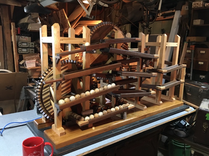
Stuart's Rolling Ball Clock
(click on image to enlarge)
Okay, there are tons of of these things out there. All different designs and sizes and shapes. Just Google "Rolling Ball Clocks" to get an idea.
I've been searching for these on the INTERNET for years and all I got was offers for kits. This fall I found the first place that offered plans for building one of my own that were reasonably priced.
I ordered a complete set of plans for only $25.00. I downloaded them (as PDF) and printed them out. They are great. Very well thought out and complete.
Here is their web site if you'd like to order your own copy:
http:/Windydaysproducts.com
These folks are very responsive and have kindly answered all the questions I have emailed to them.
With plans in hand I set about to build this rolling ball clock.
My first thought was that this project would be a great way to use up some of the small pieces of scrap wood that I've accumulated over the years from building other projects. Then I decided that this clock would look great with a mixture of Red Oak and Black Walnut (my favorite combination) but I don't have many scrap pieces of Black Walnut.
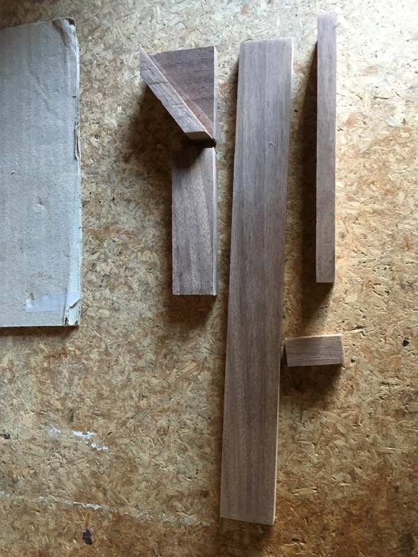
What I did have was a nice pile of Black Walnut that I'd cut for firewood last winter and stacked in my back yard.
Trim the pieces with a hatchet and then square up piece on table saw (I don't have a band saw). Shave off nice pieces of Walnut for splines and for ball track sections.

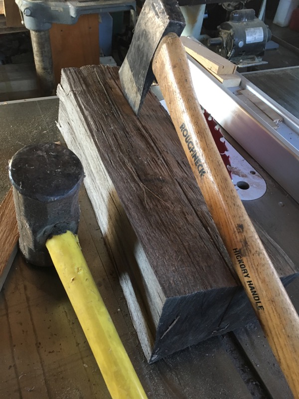
Black Walnut source

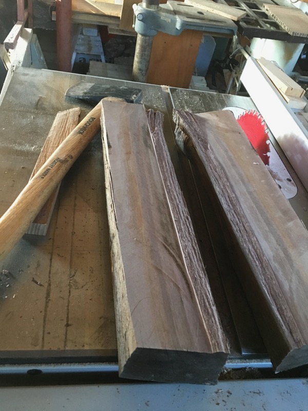
Track Pieces
Strips of Walnut sliced from billet in 10 mm width for track sections and 2mm width for splines.
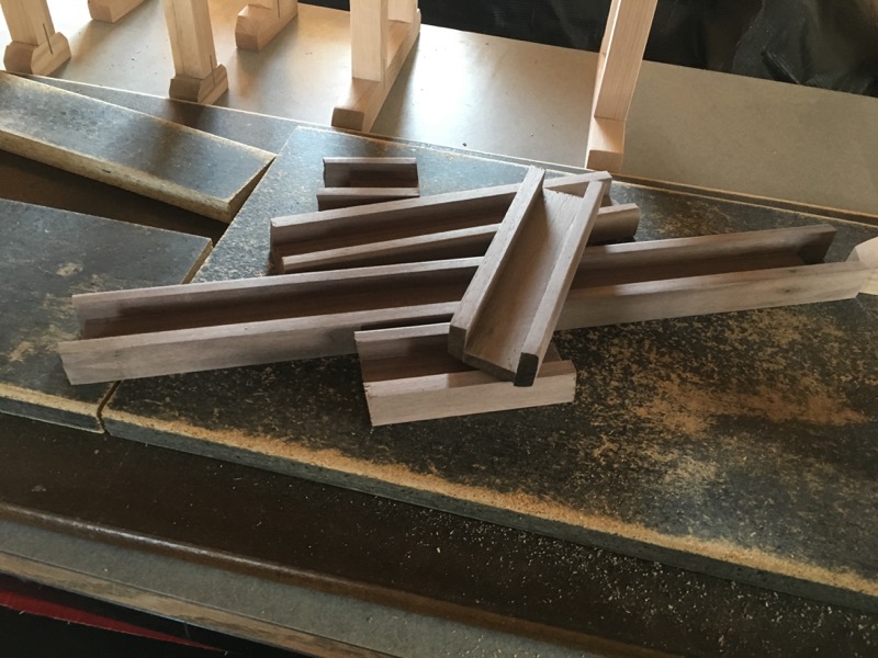
Track sections
Rough track stock glued and sanded. I decided to round-over one edge, both bottom and top, to dress up the track a bit. I left the side that attaches to the towers square for maximum glue surface.
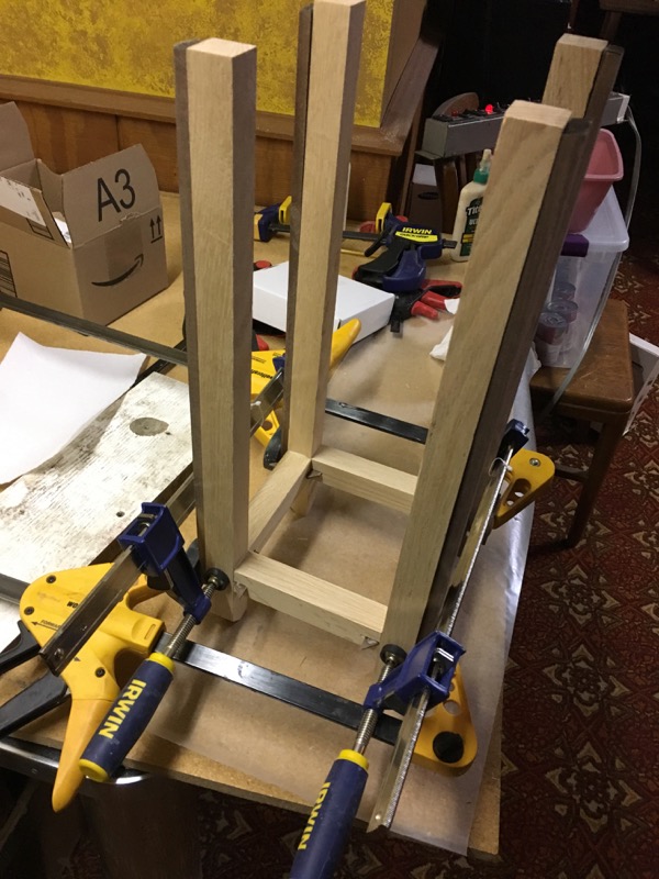
Red Oak used for towers
The track support towers are made from Red Oak and fashioned from rough cut pieces of wood that originated in family woodlots in north-west Wisconsin.
The plans called for just butting these pieces together and gluing. I made splines out of the black walnut. Splines will add a little strength and give it a nice look.
It took a bit to figure out how to spline a corner joint. I ended up cutting the spline material into a triangle. Each such spline would join one upright with two 'arms'.
Make sure the grain in the spline goes parallel to the base and that the base goes into the upright. This puts the strength of the spline grain perpendicular with each arm.
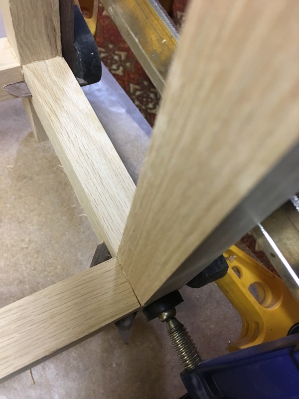
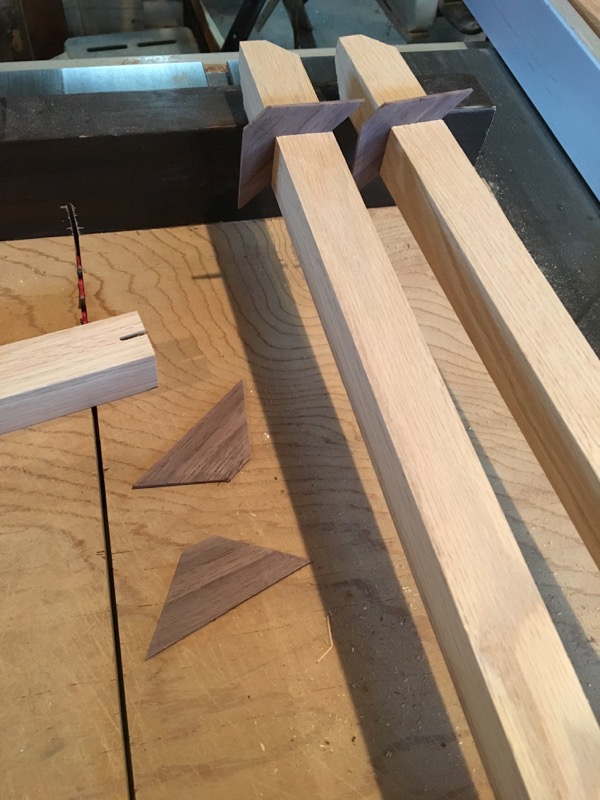
Tower Splines
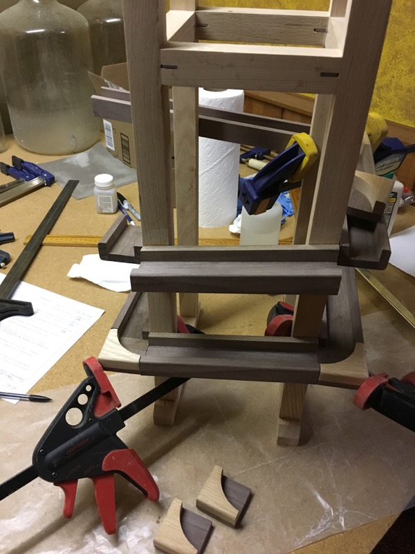
Attaching Track
building Track Corners
Track Corners
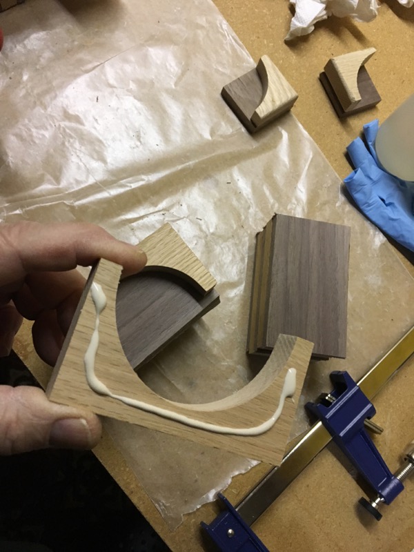
I changed up the corner sections a bit from the plans. The intent was to make them match the track in size so that it followed smoothly around the corner. Using a combination of Red Oak and Black Walnut just continues the theme.
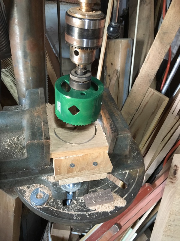

building Track Corners
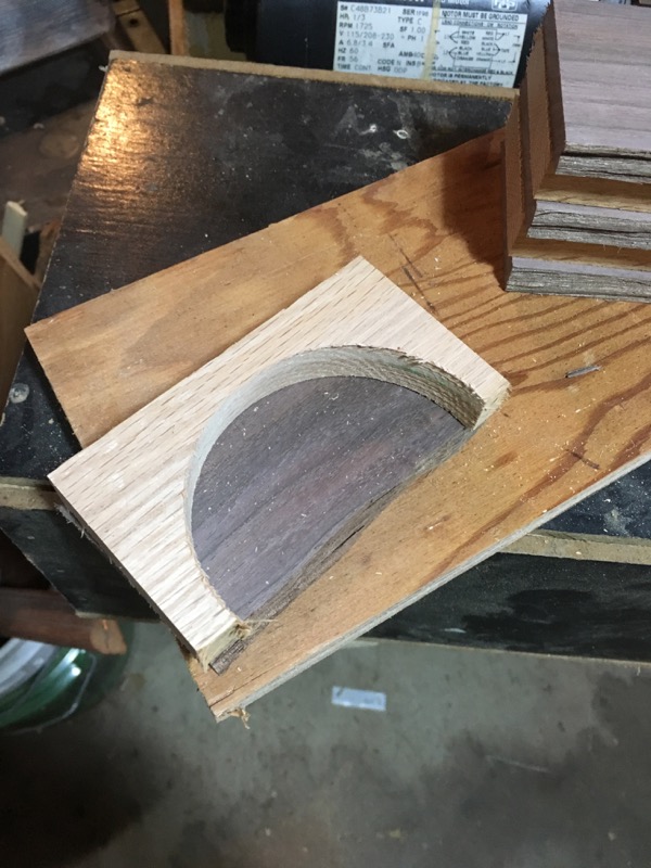
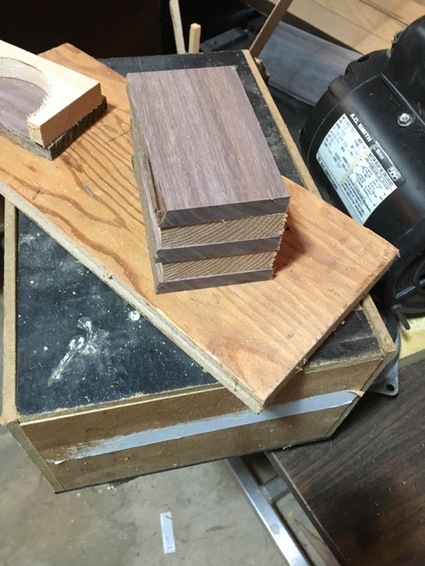
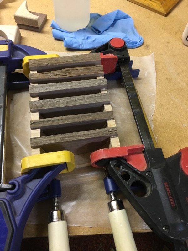
Corner sections are cut on a 4 1/4" hole saw (this cuts a radius of 50mm plus a saw curfs). This produces a half circle in White Oak that will be glued to a base of Black Walnut. These are glued and stacked together for clamping.
When the glue sets these pieces are cut in half, trimmed and sanded. The top and bottom are routed with a 3/16" round-over and then the 'inside' edges of each corner piece is trimmed to match the space it will fill. These are roughly 50mm but there are small variations.

building Track Corners (19 plus a few 'spares')
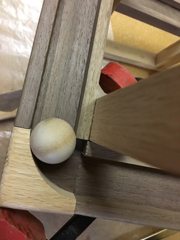
Problem: stuck ball
While trimming each corner piece to fit the tracks, I was paying too much attention to making a smooth connection to the outside of the tracks (for a clean look) and I forgot to watch the inside (ball track) as I was slicing off bits of stock. This caused the inside track to squeeze the trail so the ball would catch on the edge.
Lucky i noticed this during the pre-glue clamping. (Lucky I'd decided to order the balls before the rails were done.
So three of my nice corner pieces were suddenly scrap. Or maybe not ...
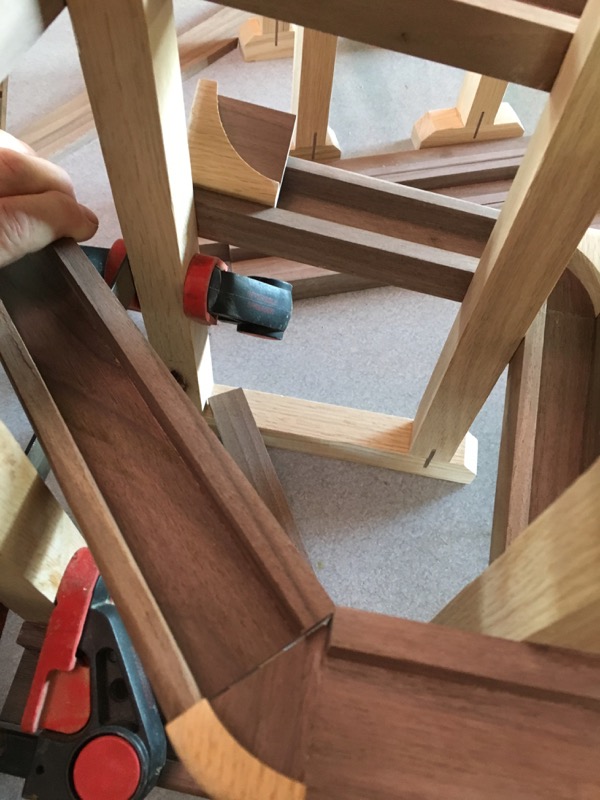
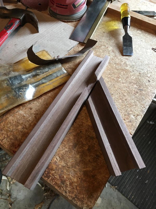
Cut through track section challenge
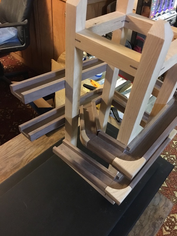
track merge (finished)
This bit is a little tricky. I couldn't tell from the pictures and plans whether this diagonal track joins the side track or just overlays it and drops the ball in from above.
I emailed the authors and they said it did merge and apologized that it wasn't clearer in the plans.
I held off on gluing the target track in place until I knew where to cut the notch.
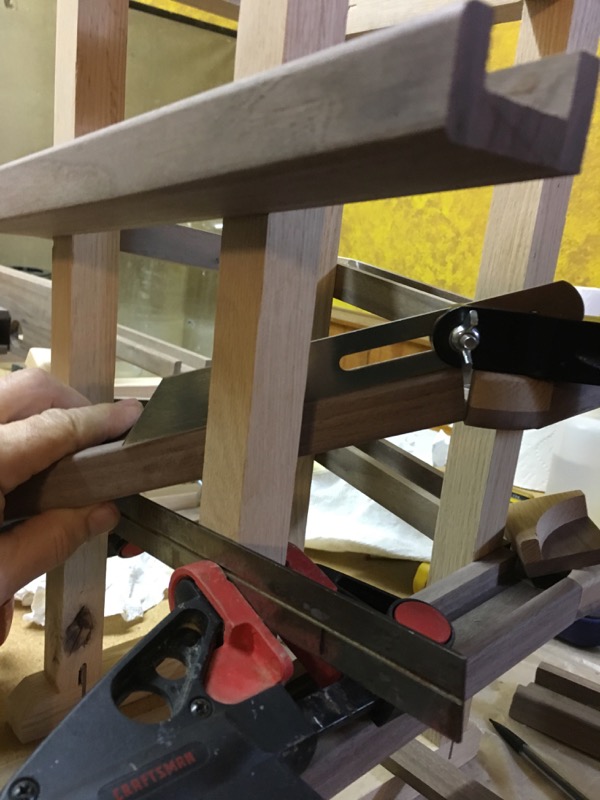
measure angle for drop
1.Measure drop angle:
All the track sections on this tower drop at 7-degrees each. This diagonal will have to be steeper in order to join the target track. Clamp a straight-edge in the position of the merge track and lay a piece of track stock in position between it and the 45-degree angle piece. Then measure this angle (20-degrees).
Cut the top edge of the diagonal track piece.
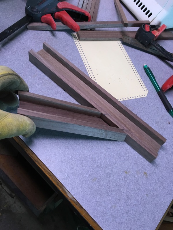
layup for merge
2. Mark compound angle for merge cut:
With top angle cut, position diagonal on straight-edge and mark bottom to get first angle.
Carefully hold the track in position and project a vertical cut up the side of the track section from the outside edge of the straight-edge to find the second angle. (a second pair of hands would have been helpful).
Set up the saw and cut this compound miter cut. (of course the first try came up a little short so I had to make a second piece. this time I started with the compound end and then slowly shaved off the top a little at a time until it fit.)
3. Cut out notch in long track section:
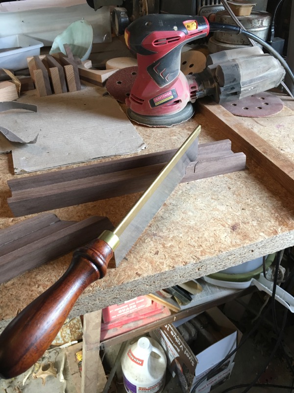
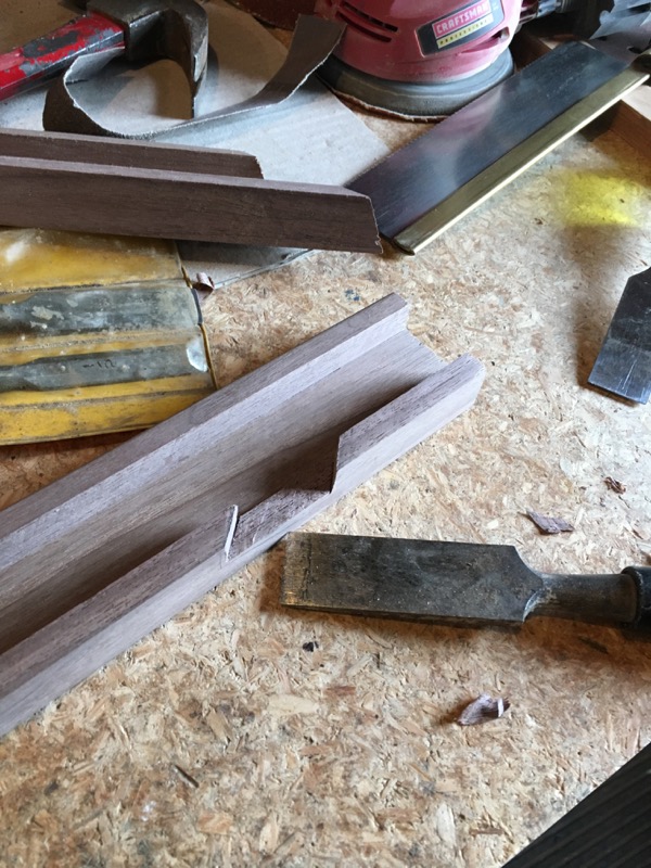
Cut out slot for merge track
layup for merge
4. Glue in place:
I'll leave it to you as to how you want to glue and clamp this piece in place.
There's another of these merges in tower #2 so I'll tackle that while this is fresh in my mind.
stay tuned....
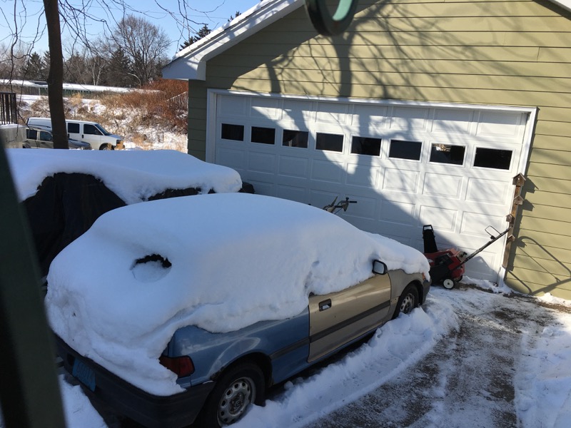
it's cold out there
If it seems to you like this project is taking a long time to build, it seems that way to me too.
But I live in Wisconsin and my workshop is in my unheated garage . When my fingers get numb, I quit for the day.
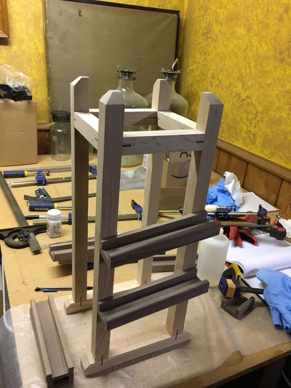
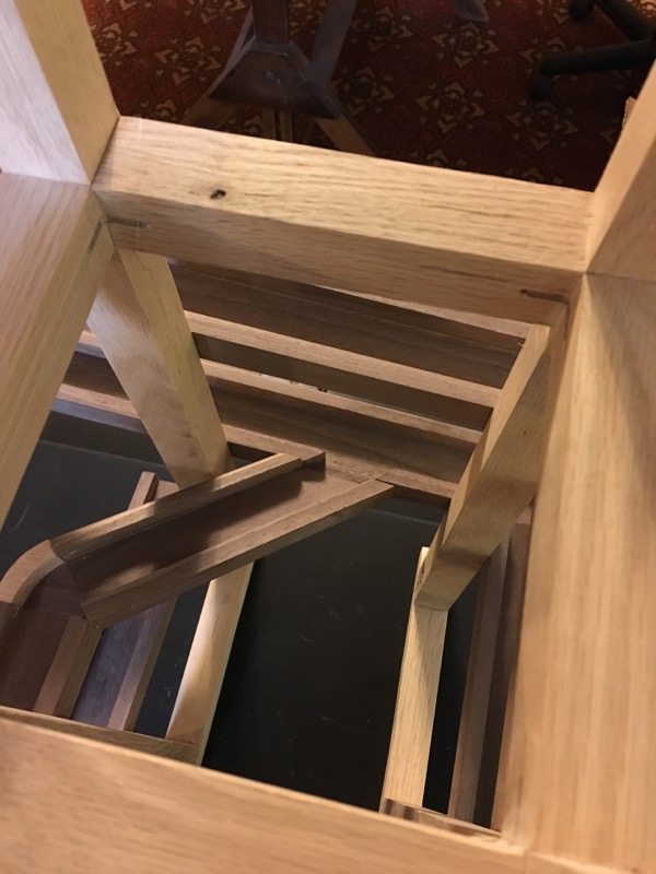
Time Racks
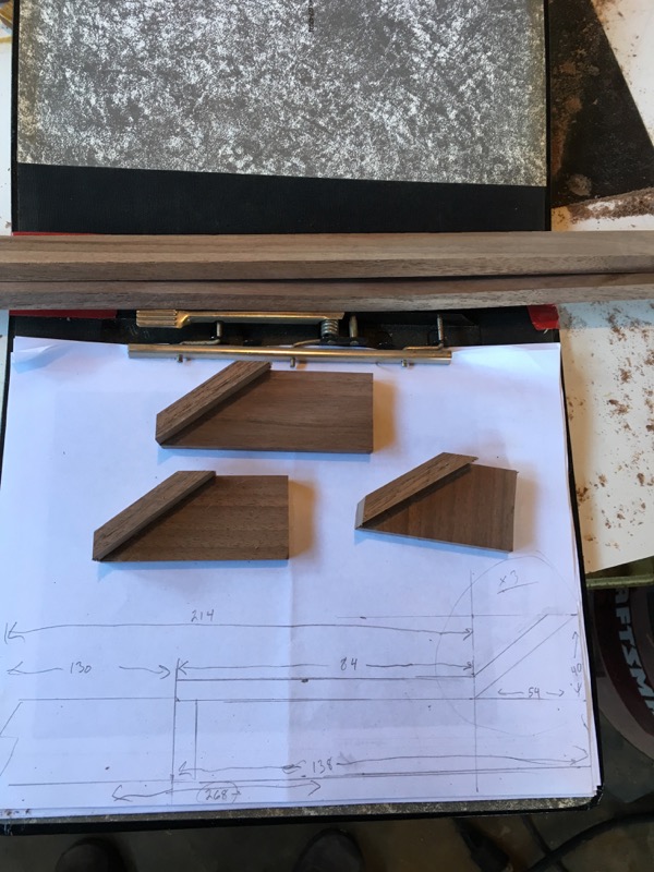
 cut pieces for racks
These three 'teater-totter' track pieces are where the balls line up to show the time. These are a little trickier to make because of the expansion at one end.
Many places in these plans, I found it helpful to draw a full scale picture of the piece and then work from that.
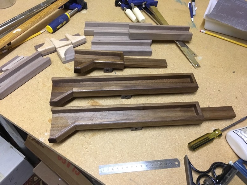
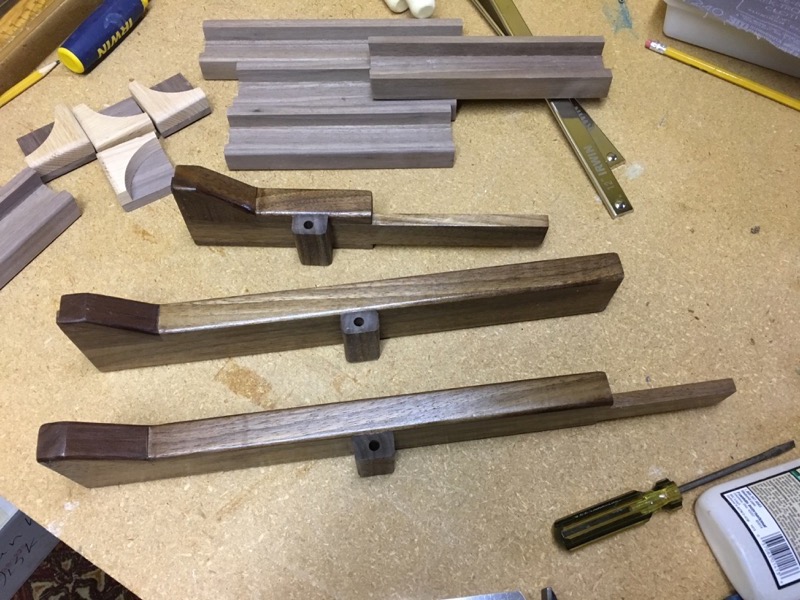
Time Racks assembled and finished.
Top view and side view of glued and finished time racks. The trail sections above have now finish applied. See how the Poly brings out the color and grain of the Walnut. (click on pictures for larger view )
I have added the pivot blocks on the bottom of each rack.
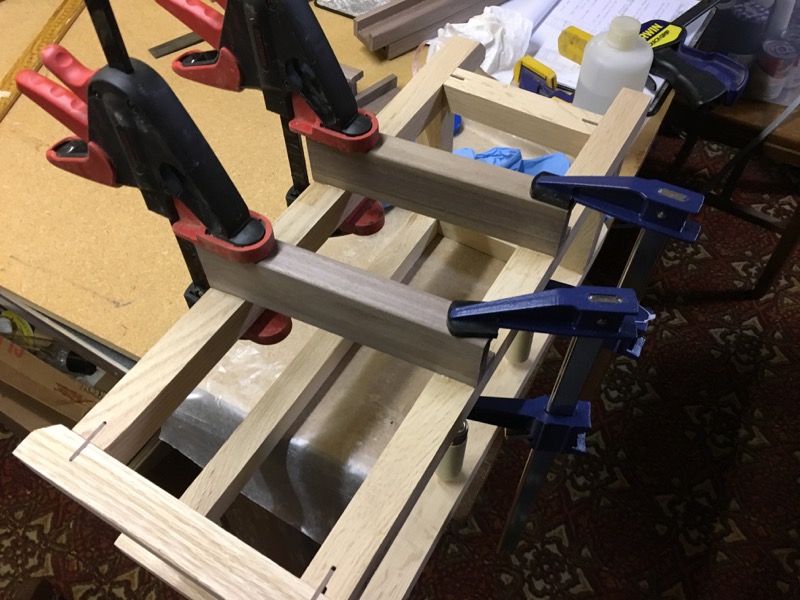
Begin to apply finish
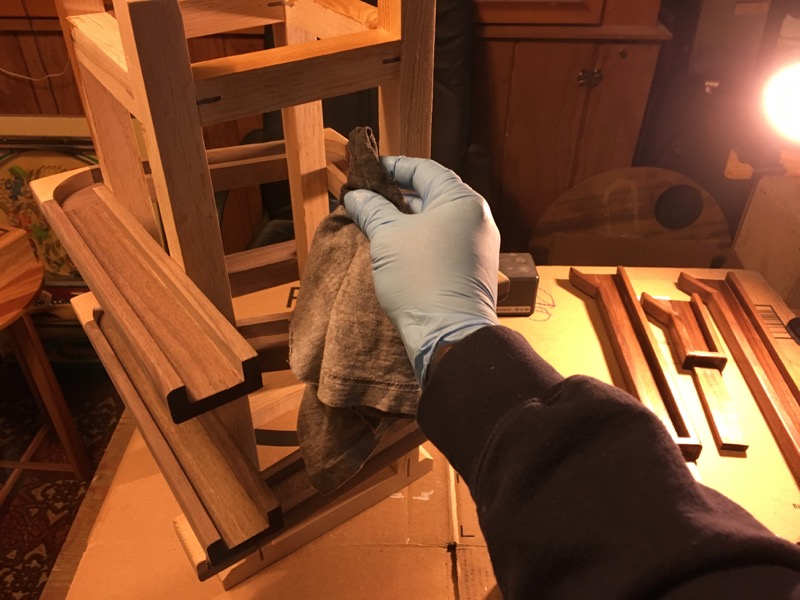
Apply Polyurethane
The first tower (right) has all the tracks attached so it's time to put on the first coat of finish.
I use a cloth instead of a brush because of all the nooks and crannies that can catch the liquid and cause running and droops and other problems.
See the finished racks on the right.
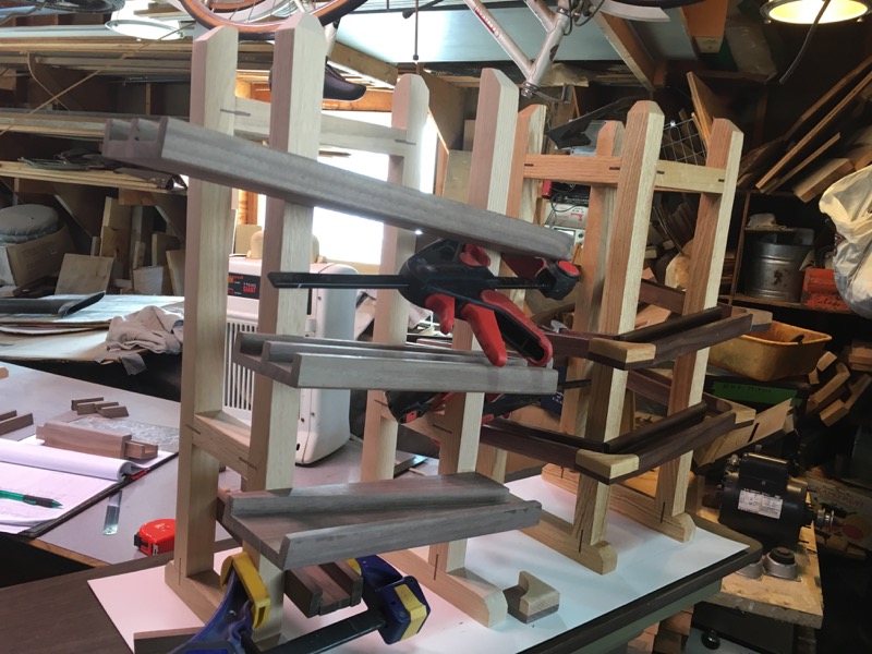
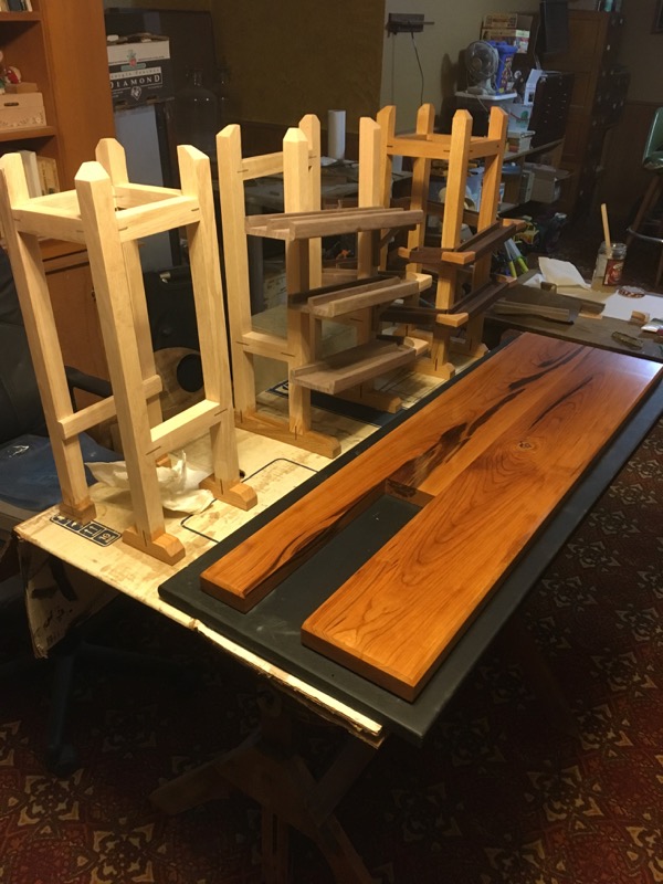
compare
See how the finish brings out the color of the wood. Unfinished tower in foreground.
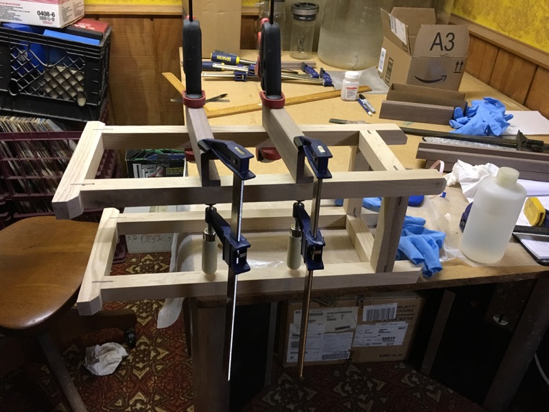
Building a base
As soon as I started attaching track sections to tower two, I quickly learned most of these were just a continuation of the tracks on tower one; and they had to match exactly.
It's time to fix the two (three) towers in space.
It's time to build a base.

first base
I had some particle board, left over from some old brick and board shelves, that fit the dimensions so I cut it up and painted it black. I really don't care for particle board and I thought this was a pretty tacky addition to a piece of 'art' that I am trying to make.
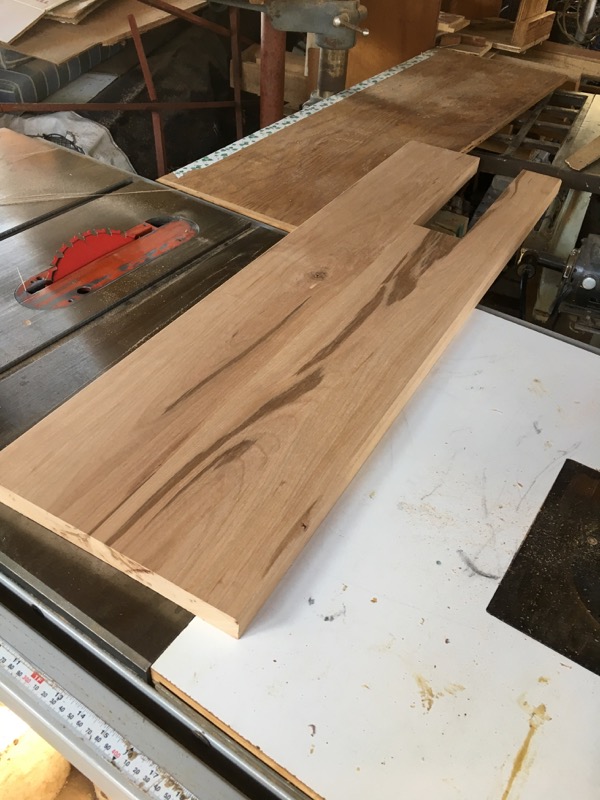
second base
I found a nice piece of Black Cherry in my attic that will make a nice base. It has a couple knots and some staining so it is perfect (perfectly beautiful ) for this project.
I've ripped the board and cut a shorter piece for the center. Then I glued them all back together and side by side to make the base with the notch for the bottom ball wheel.
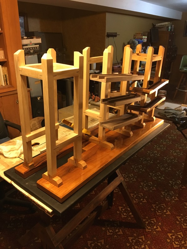
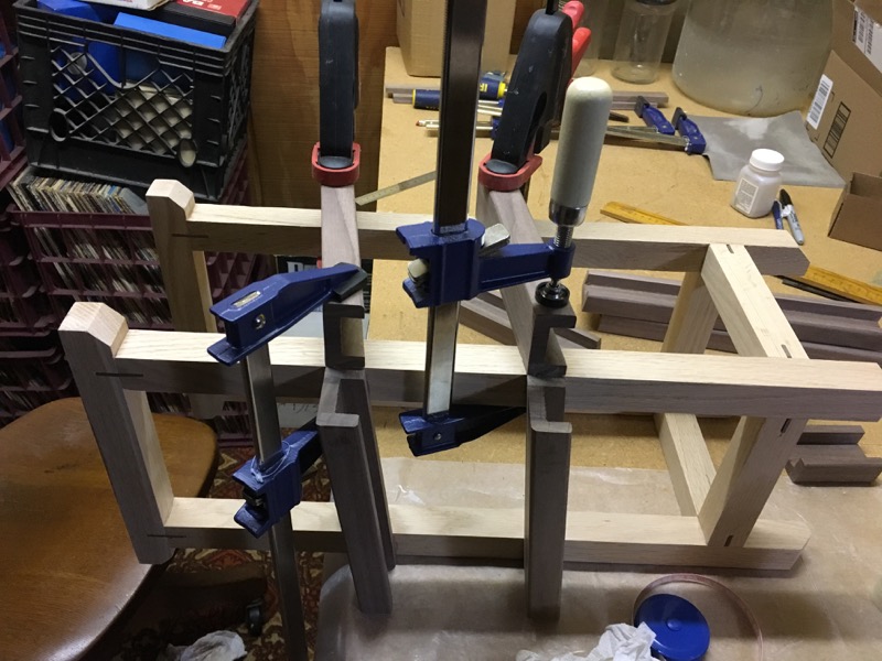
Set up towers
Now time to place the towers on the base and install the remaining track pieces.
I am just clamping things in position for now and will actually attach the towers as soon as I have all the pieces in place.
There must be a better way.
(March 2018)
So far I've been building the tracks for the balls to run DOWN. Now it's time to work on getting the balls to the TOP.
This is done with two geared wheels; each one raising the balls half way to the top.
These wheels each are 320 mm. in diameter and have 64 gear cogs (teeth) on their circumference. The instructions call for gluing each tooth along with a spacer onto the wheel. This seemed like an awful lot of work to me so I built a jig that allowed me to cut a dado for each tooth.
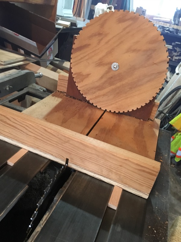
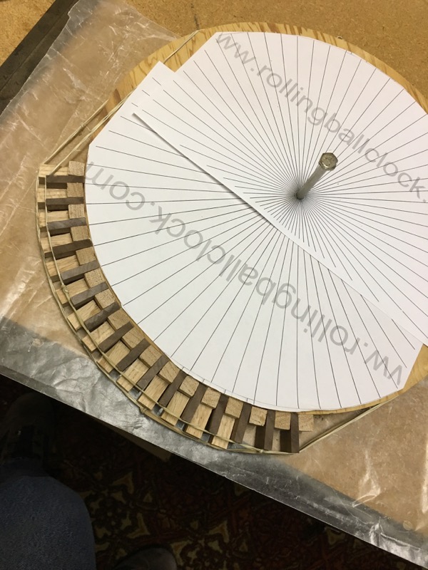
Gear
Cutting teeth
I set up this jig on the end of a slide that passes the wheel over a dado blade set to 1/4" width (~ 6 mm. ). I drove a small screw behind the wheel, 15 mm from the slot, to act as a gage. Once a slot was cut I would rotate the wheel and put that slot over the screw to line it up for another pass.
This worked great except that when I got all the way around the wheel I had 20 mm gap remaining and had cut only 60 slots. (not enough space for the remaining 4 slots required).
So obviously either my measurement was off or there was too much slop in the system.
Time for plan 'B'.
Oh alright. I'll try it your way.
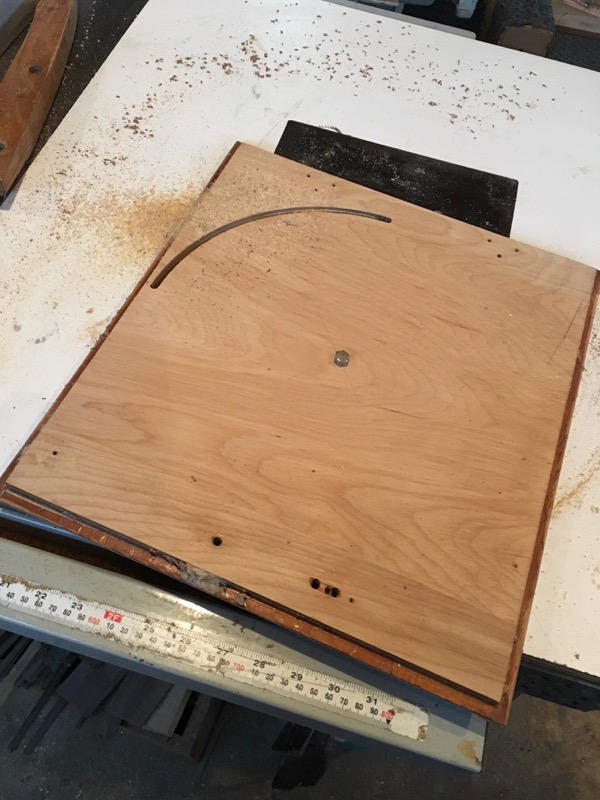
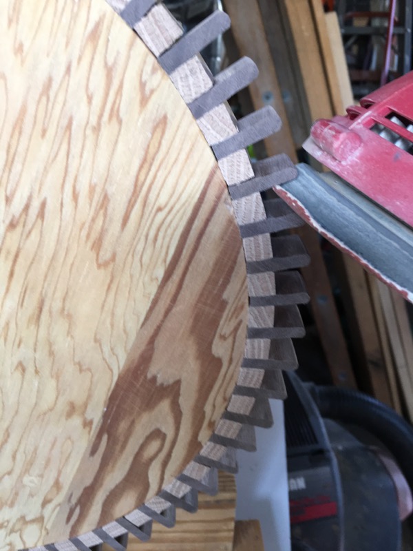
Citing disk with router
I cut another disk out of 3/4" plywood (~20 mm.)
Instructions call for a disk thickness of 30 mm. with teeth 20 mm wide and centered around the circumference. I couldn't think of a good way to center all these teeth so I made disk 20 mm thick and will veneer 5 mm. layers on each side after the teeth are glued and sanded smooth.
I ripped White Oak into 10 mm. X 10 mm. strips and cut these into 20 mm. lengths. Then I ripped Black Walnut into 5 mm X 25 mm. strips and cut these into 20 mm lengths.
Gluing teeth (like pulling teeth -- but the other -- opposite thing )
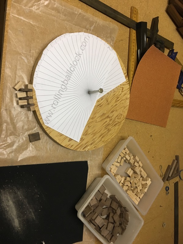

Gear teeth and spacers
The plans come with a template that guides the placement of the teeth. This prevents what happened to my first try by alerting you to any deviation from proper spacing of the teeth.
Since this disk is 20 mm. thick -- the same as the width of the teeth and spacers -- I can sand the whole thing flat after the teeth are all assembled. This will even out any irregularities in gluing and smooth the edges of the gears nicely.
Adrift in a sea of teeth

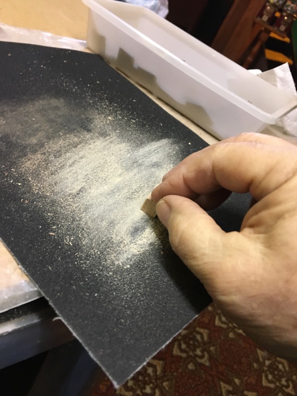
Adjusting the spacers
Right away I noticed that my spacing was drifting a bit from the spacing on the template. The spacers were a hair too large.
Actually the spaces the spacers are filling are not strictly square in shape - but more like a trapezoid -- narrower at the bottom than at the top of the cog. So I sanded each cube on two opposite faces (cross grain) and pressed on one side to take off more on the 'inside' part that would face the wheel. This turned out to be exactly enough to make the teeth match the template exactly.
More gluing teeth

Gear teeth and spacers
First lay out a series of teeth and spacers against the wheel. Watch the template and sand more or less from the spacers to keep things in sync.
Move the wheel away and apply a layer of glue to the edge of the wheel.
apply glue to each tooth and spacer in turn and position against the wheel in its final position.
Finally stretch rubber bands around the wheel to hold the teeth and spacers against the wheel for the glue to set.
I used spare spacers set on end to push the glued spacers against the wheel for gluing.
Gage how many teeth you can apply in each sitting by how fast your glue dries and how fast you are at getting everything in place before things set up.
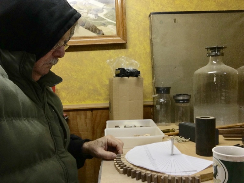
Me, gluing teeth
It's warmer in our basement than in my workshop so I can use the glue and various finishes, but it's not warm enough for me to work comfortably.
Dressing up the gears
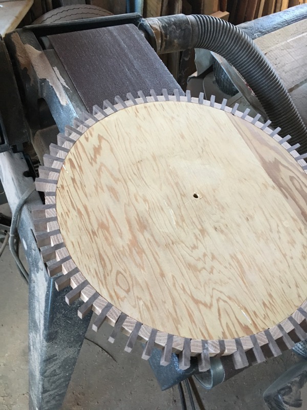
Dressing up the gears
The original plans called for these gear wheels to be 30 mm thick and the teeth and spacers 20 mm wide and glued to the center of the circumference. I felt like this would take too much precision to get it to look neat
To that end I am here smoothing off the edges of the wheel and the attached teeth with a belt sander.
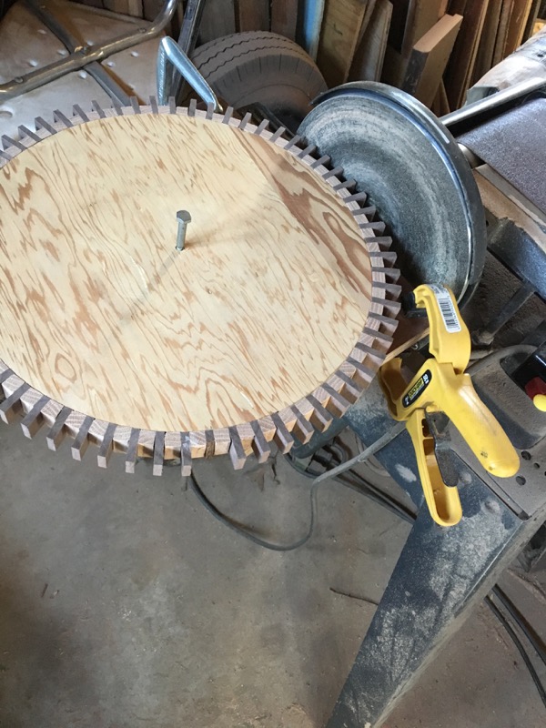
I will apply a 5 mm thick 'hubcap' to each side of these gears to bring the total thickness to 30 mm.
After setting these two gears on axles and testing how well they mesh, I discovered that any deviation in the positioning of a tooth will cause it to jam (and break off). So I actually had to pull a few of these teeth and straighten them.
Here I have built a simple jig to spin the wheel against a disk sander to even out the tooth tips.
To lessen the chances of the teeth hitting an opposing tooth on the other gear, I rounded down the edges of each tooth (top and bottom).
Hub caps
Hubcaps
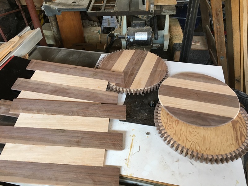
To make the gear faces a little more interesting I sliced some 5 mm thick pieces of Walnut and Red Oak and glued them together; edge-wise.
I cut the resulting sheets into disks before I realized the Walnut wasn't as dry as I thought it should be. After a few days sitting in my shop these round disks took on an oval shape. (remind me to tell you about my ball tracks) .
I hung these disks behind my wood stove for a couple weeks in order to dry out and then I cut them into a slightly smaller disk -- which should hold their shapes.