Classic Valley Spectra IV table top, four station pinball game.
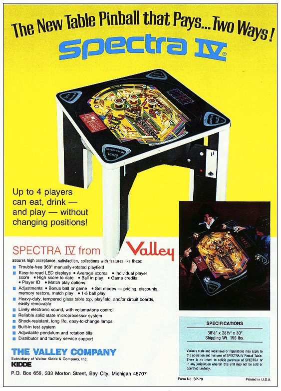
Sales Brochure for Machine (click to enlarge)
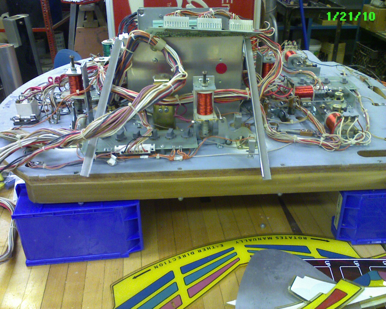
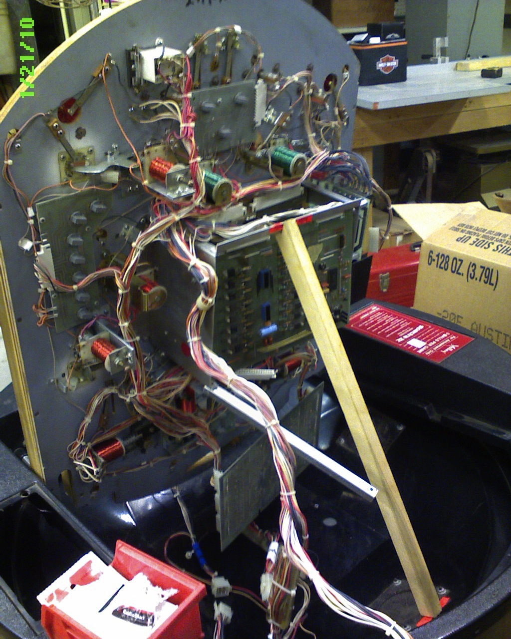
My first view of this machine was the play field upside down on the work bench. The owner said he'd gotten it from a friend who said it worked when it came to him. It hasn't been used for many years and the last time it was fired up it blew fuses.
I began by disconnecting the main power supply from the game and began testing voltages. First the output of the transformer and then the output from the bridge rectifier.
The main power supply provides two 12V AC feeds to the game board (input for the 5V / 12V power board mounted on the game). It also supplies either 40V or 35V (through a DPSP switch and a bridge rectifier) unfiltered DC for the solenoid drivers.
I spent a great deal of time on this - mainly brushing up on my electronic theory - and ended up replacing a couple switches and the rectifier. It seems strange to me that the AC ground for the 12 V lines is common to the DC Low side of the 40 V DC as they feed the game. I was seeing some strange voltages as soon as I plugged in the game.

First look at machine
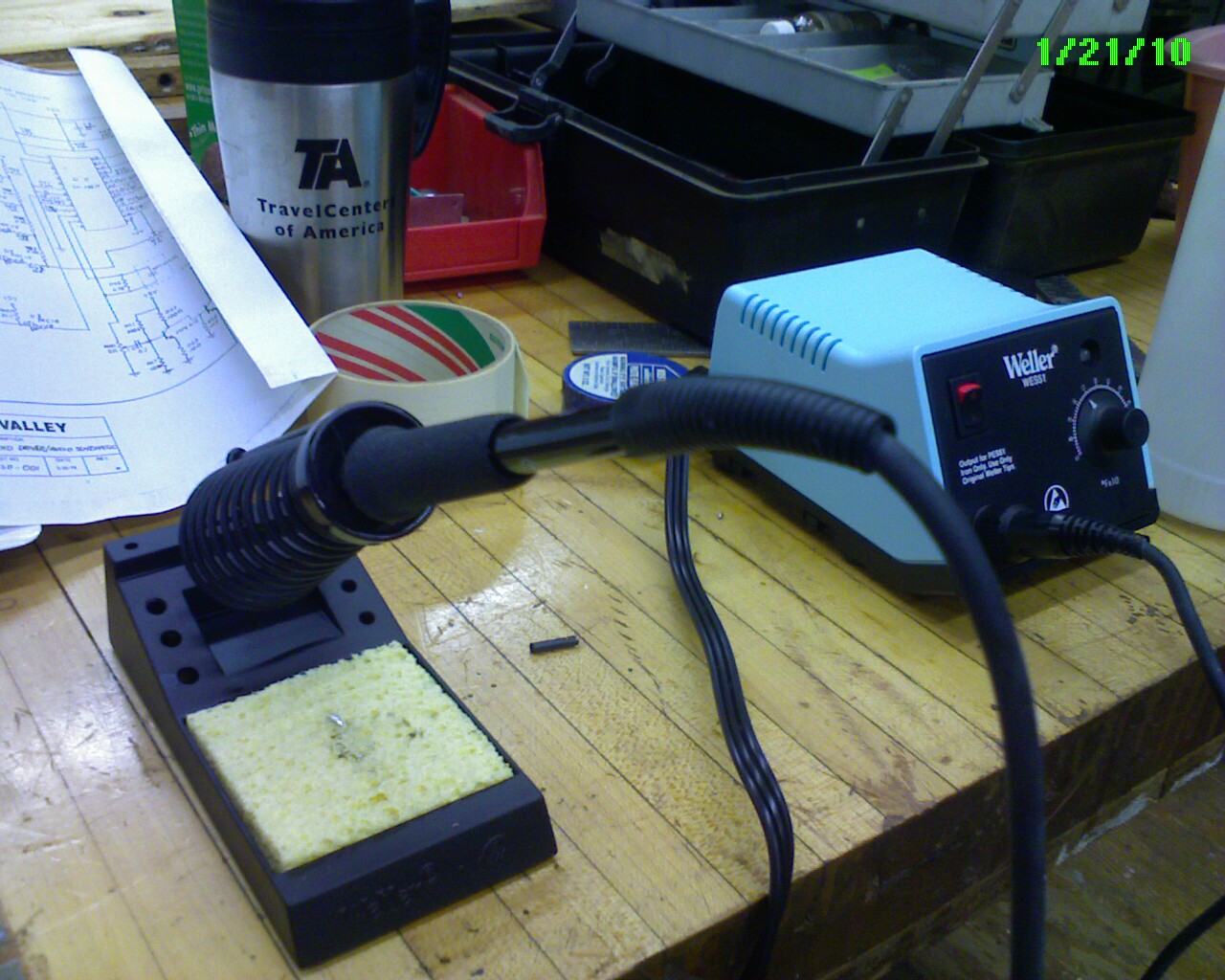
Weller Solder Station
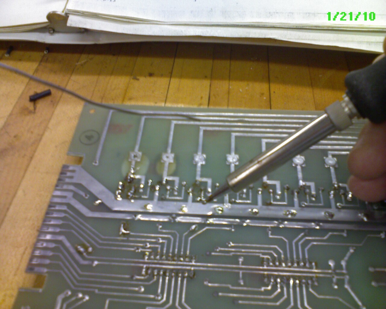
Back of relay driver board
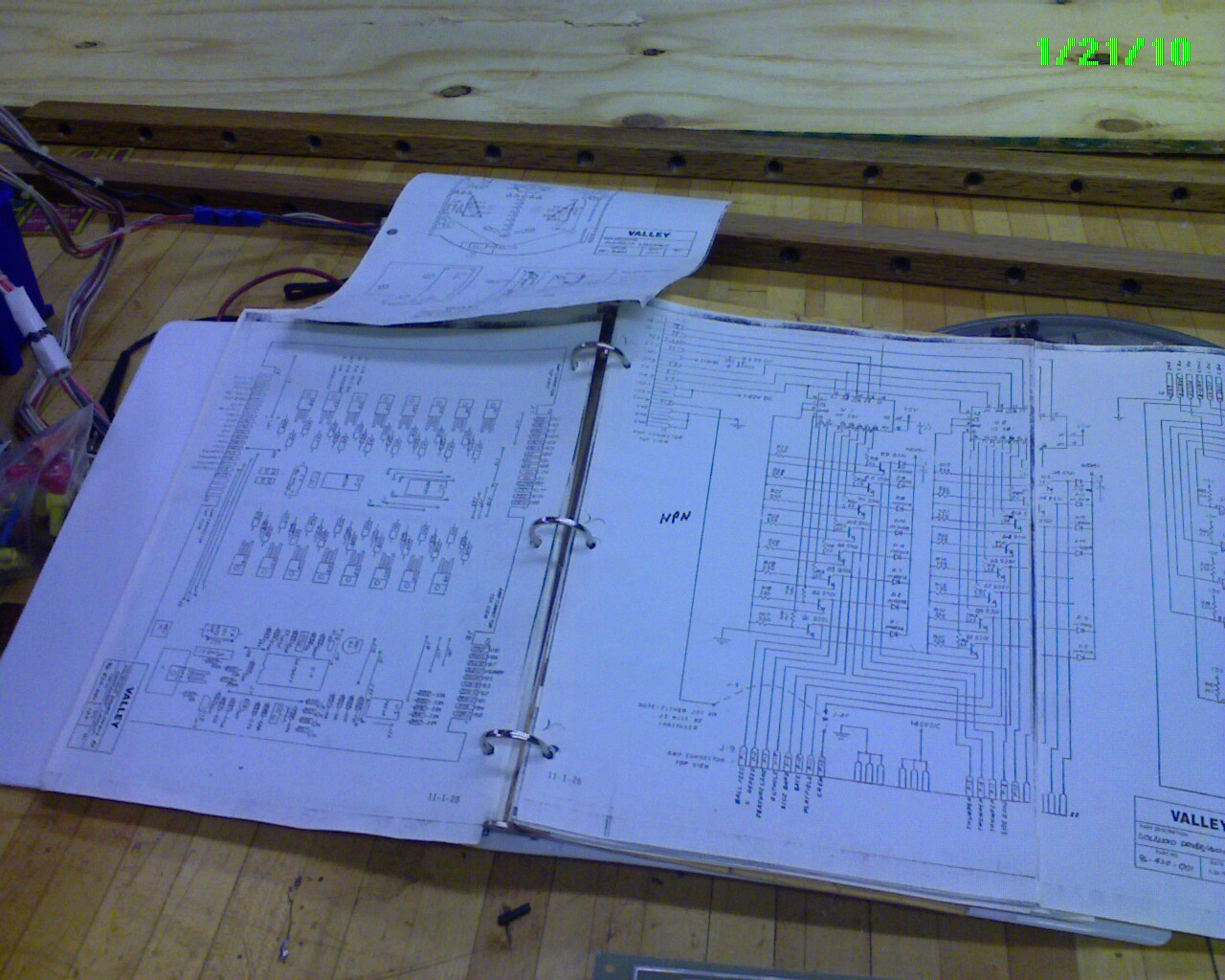
Valley Spectra IV User Guide
The manual found with the machine was a copy and the pages were out of order and some were two page fold outs that needed to be taped back together. Having a logical organization to this manual is time well spent and saves time later when looking for circuits and components.
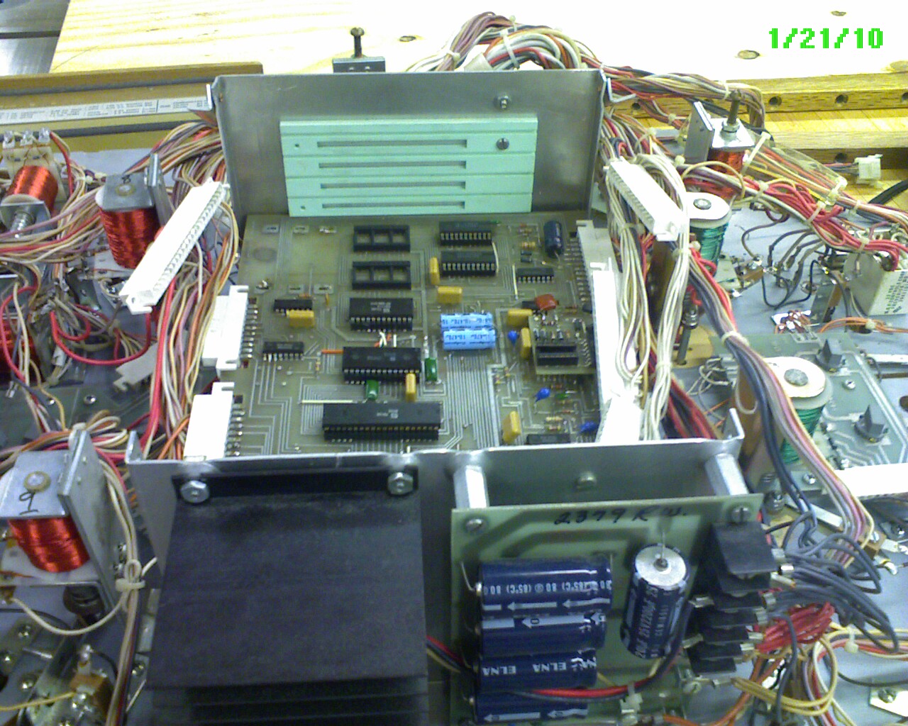
Card Cage with MPU board
This machine has three boards - from bottom to top (while playfield is laying upside down on bench):
1. CPU / Memory board
2. Solenoid driver board
3. Light driver board.
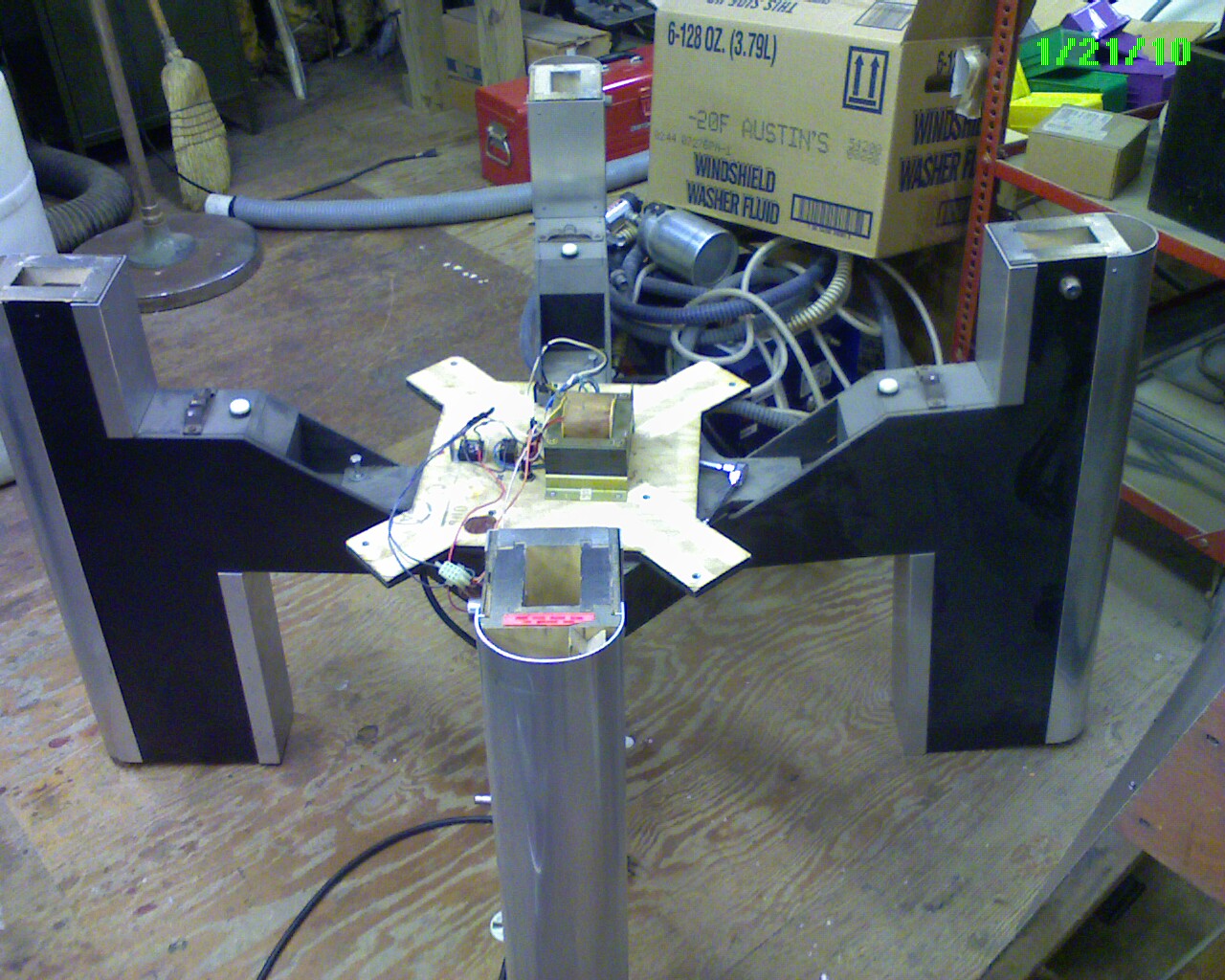
Table with play-field removed
Main power supply board sitting on top of the table leg assembly. This mounts underneath the center structure and is not particularly accessible. All legs need to be removed and the center assembly (hub) removed. The transformer is a split secondary with 12V center tap and a 35/40 volt winding. I'm still not sure why they provide two voltages (for the bumper solonoids) but these are switch selectable on the bottom of the machine.

Under side - lower game
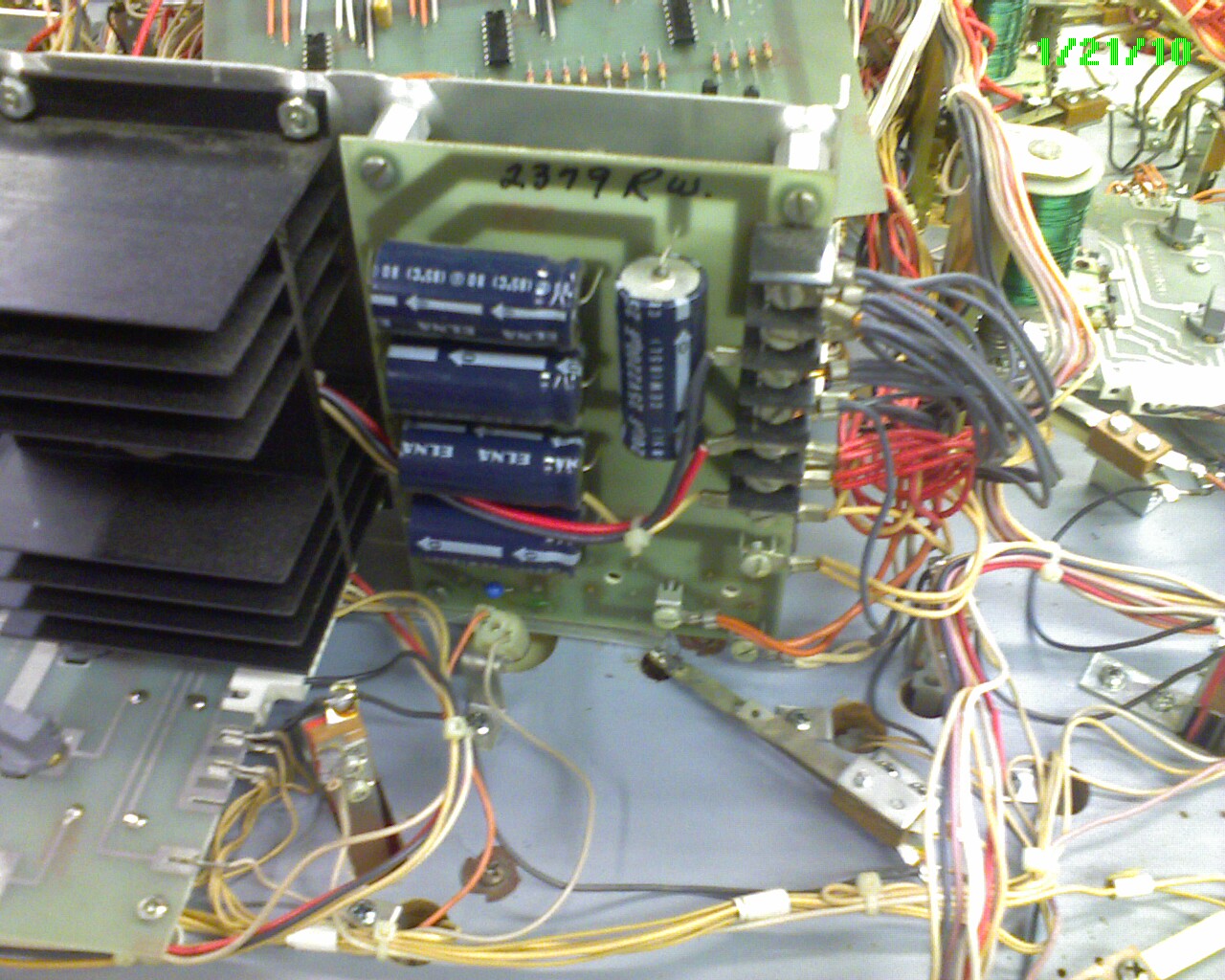
DC Power Supply
When I first plugged in the game I was seeing over 2.0V ripple on the 5 V power. I replaced the Capacitors and this ripple disappeared (< 1mV.). This is where a scope comes in handy. Otherwise you need to compare AC and DC readings on a DMV.
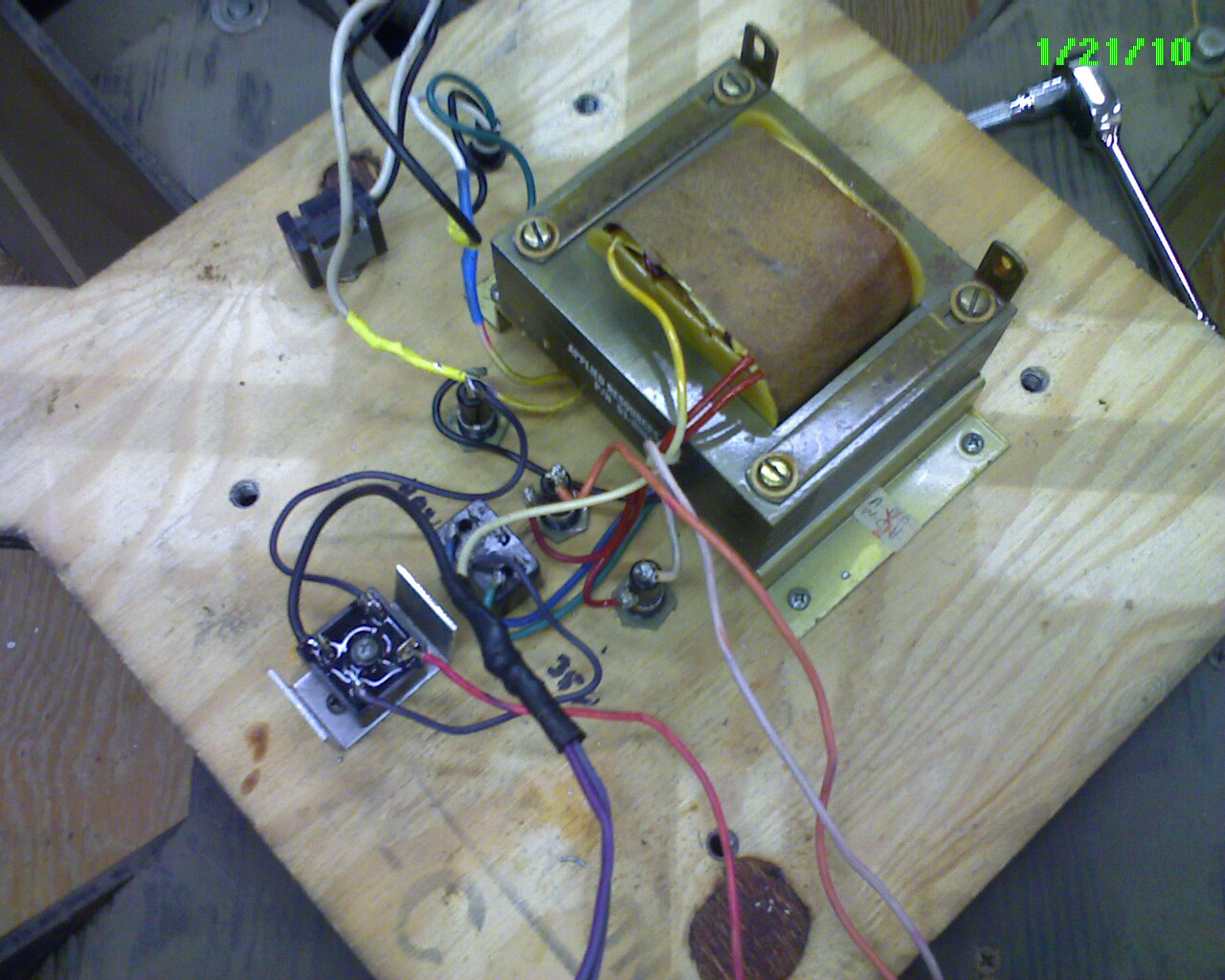
Main Power Board
Close look at the main power showing fuses, transformer, power switches, and the rectifier for the 35/40V solenoid drivers.
I replaced the main power switch, bridge rectifier and verified all power was okay for both 12V (full-wave rectified but NOT filtered) and 35V AC and 40V AC before connecting to slip ring assembly.
NOTE: The main power switch needs to be DPDT so that it switches BOTH (L1 & L2 ) of the 120V AC in. I don't know why but if this isn't done some problems that come up with the 5V power supply are not cleared when power is cycled. (any ideas? )
Under side of upper play field
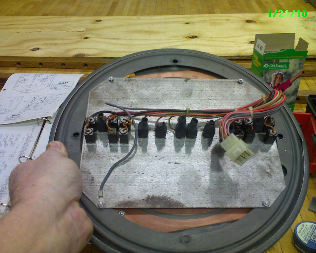
Slip ring assembly
This table rotates so that four players can sit at the table and rotate the game as each takes their turn. These carbon contacts transfer main power as well as signals from the coin box, tilt mechanism, score display board and speakers between the table and the play-field assembly.
You might think this would introduce noise in the power which is probably why all filtering and final power regulation is done AFTER the slip ring. Since some signal lines still must pass through the slip ring there are some active cable filters added to the main harnes.
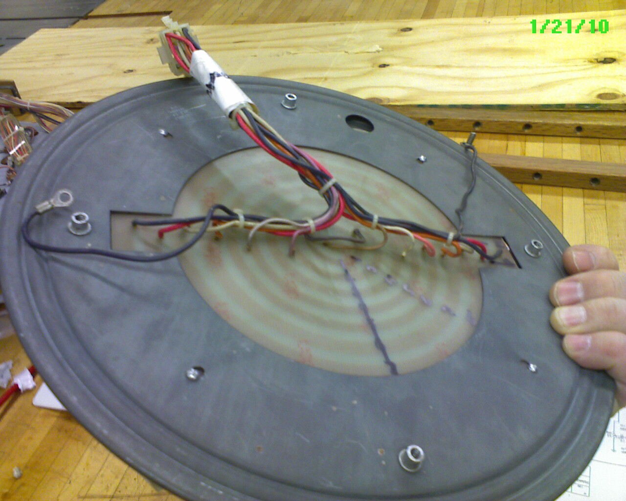
Slip Ring
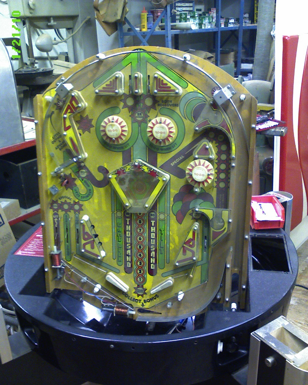
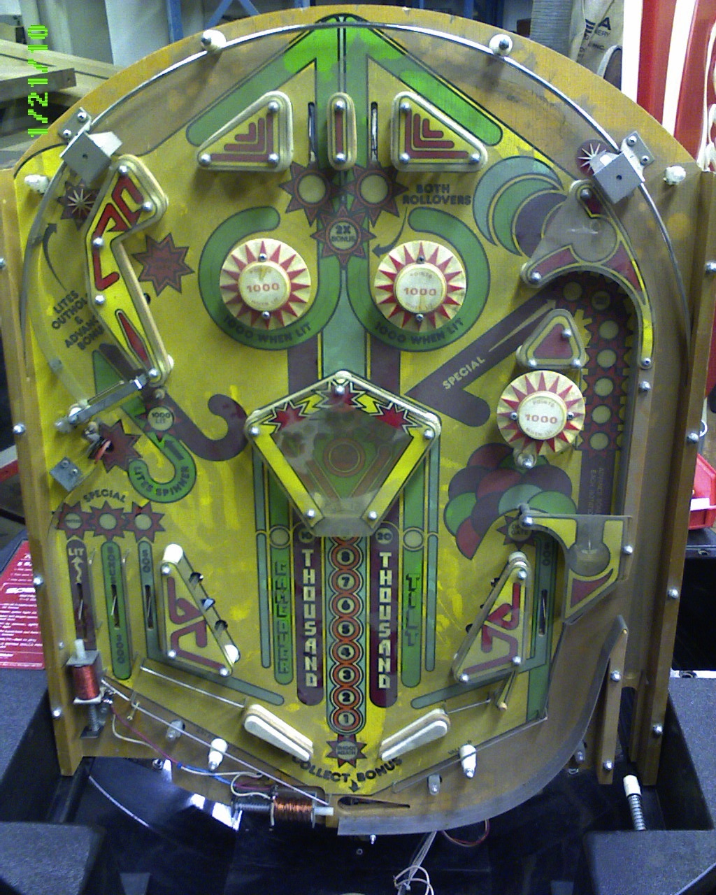
Play Field
This is a view of the play-field reinstalled in the table "Tub" and tilted up in the service position.
play-field under side
Play Field

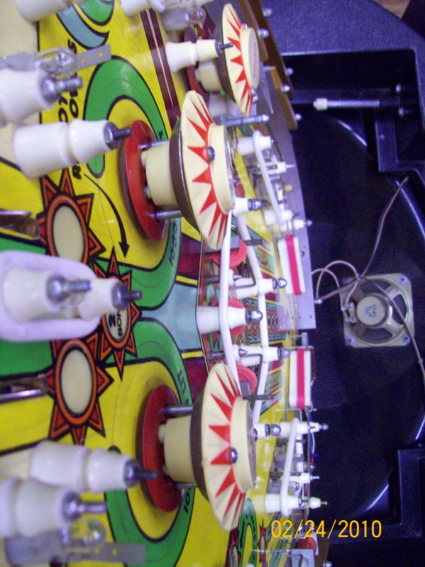
Ring Set
After everything is working (mostly) it's time to replace the rotten rings (all of them).I searched the internet for suppliers and found a few. Most had Ring Kits already made up for the popular games but this game seems to be very rare and very few sites even know about it - much less provide parts.
I found a good source at a local arcade game /pool table dealership. Bullseye Games, Madison Wi. I took all the old rings and posts over to their parts department and they very kindly set me up with all the new parts (no wasted time or money). Thank you, Doug.
Here is a list of the rings that were needed:
| Number of rings | Size (inches) | Location of Rings |
| 1 | 4.5 | Center Island |
| 2 | 3.5 | Bottom Side Bumpers |
| 1 | 2.5 | Left Side - Lower |
| 2 | 2 | Top (right and left) |
| 1 | 1.25 | Right Side |
| 2 | 1 | Top left and Top Center |
| 4 | Large post | Various |
| 5 | Small Post | Various. |
Shots of the table after cleanup:
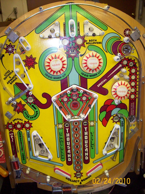
After cleaning....
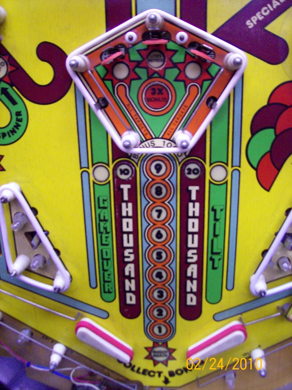
top down view
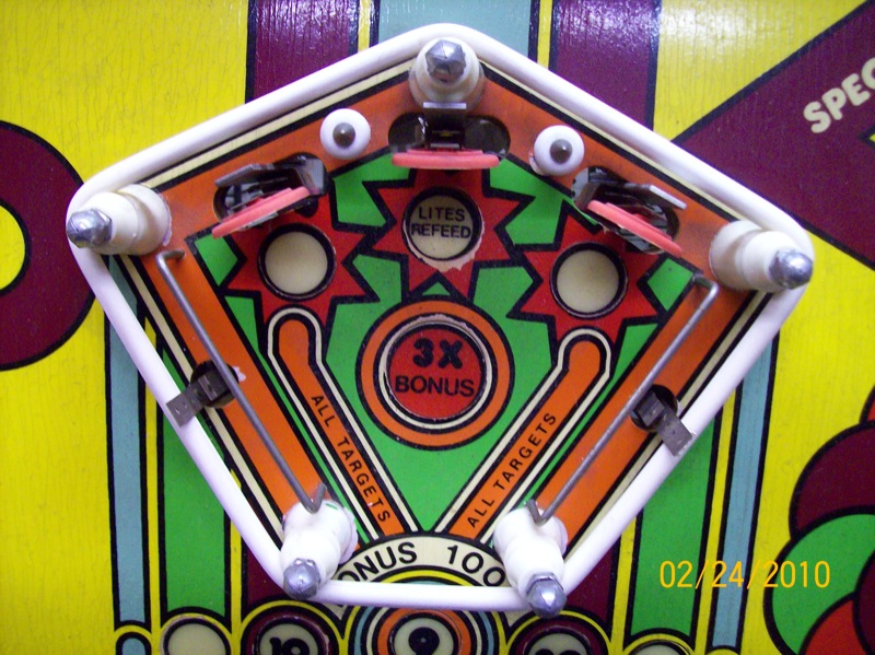
Center bonus
Bottom
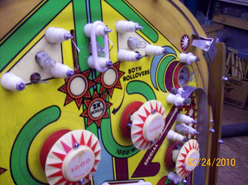
Top
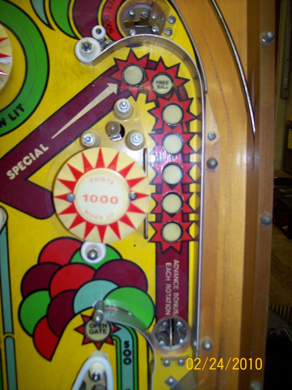
Bottom
Thank You:
I have received many calls and emails from folks who have these machines taking up space. One gentleman, who lives near Detroit, had two and we were able to manage the transportation problem and now these machines are in my basement.
Update (2012):
I have been working on this machine for two years but I still don't have a working machine. My original unit is still the best I have seen. There is no damage to the mother board from battery leakage and I have actually gotten the machine to work properly (both diagnostics and actual play). Now for some reason it has stopped working and all it does, when power is applied, is to light up the board and sound the startup tone through the speakers. The spare machine that I have obtained does the same thing. I have been working on power supplies and filtering both at the supply and at the components on the motherboard.
I have to assume the processor is working because the startup 'song' plays (assuming this is some sort of POST message). The control program either fails or the circuitry that tells it to run (indicates run mode) is faulty. I was thinking about how useful it would be at this point to have some documentation on the software that runs this game and I have just become acquanted with the gentleman who may be the only one to get one of these machines working. He has a web site where he has published much information about the software that runs this game. Here is a link: http://www.rustykey.com/projects/spectra/page1.html
Update (2013):
BIG NEWS! I've been contacted by a fellow in Ohio who is working on a prototype for a replacement MPU board for the Spectra IV machine. I recently had a long talk with him about this project and am convinced that it will work. As I have said, I would love to tackle this myself but I know just enough to be dangerous (probably) and it sounds like he is in this field and does board design and fabrication all the time and that's what it will take to pull this off.
He is trying to figure out how many people would buy such a thing because there is quite a bit of effeciency of scale with this sort of project. If he can sell 100 rather than 10, he can get much better prices on the parts and he can spread development costs out over a larger number of sales.
After our talk I am convinced that further work on these old MPU boards is futile and I will be shelving my recovery efforts until I see the results of his work on a prototype.
If you or someone you know think you might buy such a board, please contact me and I will pass either pass along the numbers or put you in touch with him directly.
Onward and upward. We'll get these things out of the realm of coffee tables yet.
Stuart