Building MORE Rolling Ball Clocks - scale models of original.
December 2018: Six more towers - 80% smaller. (actually 7 more when counting one 'oops')
Ball Clocks II & III
My original idea for building a Rolling Ball Clock was to make use of the old Bingo Balls from our Wednesday Bingo at Goodman Community Center. These balls are 7/8" (<23 mm) in diameter. After about a year in use, the numbers on these balls become unreadable and we order a new set. The balls are still fine and it's a shame to just throw them out so I thought this would be a nice use for them.
Now that I've built one clock (we'll call it full-sized) I feel comfortable adjusting the scale to 80 % and building another. And while I'm building another, why not build two.
I won't repeat the details for building these pieces except to talk about changes to either the technique or the design.
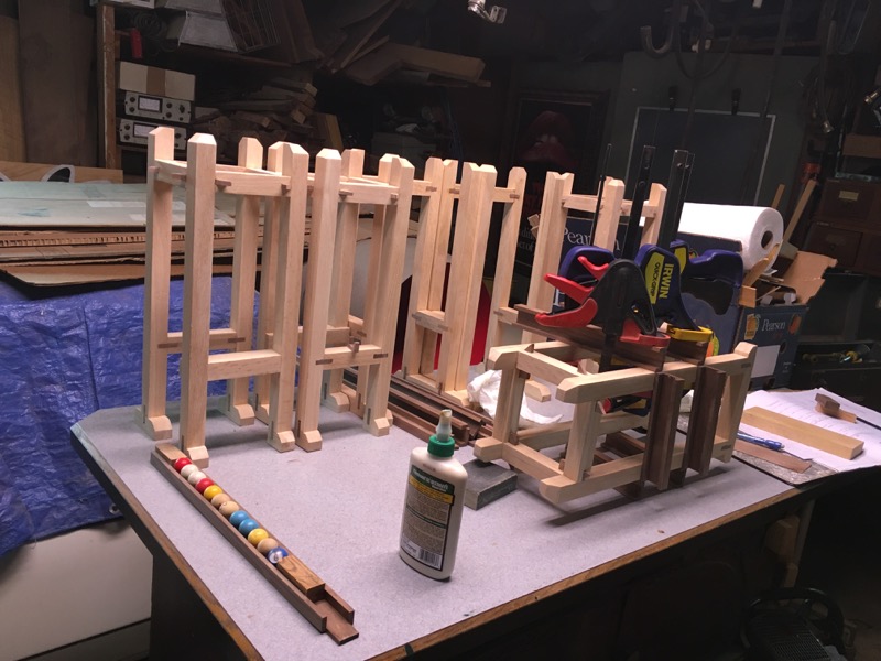
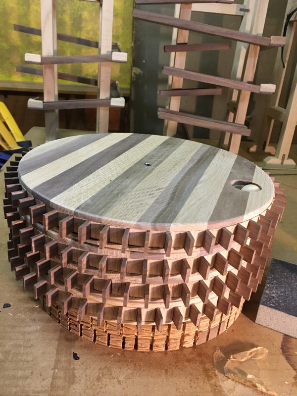
Here are the six towers and I'm beginning to attach the tracks.
Ball Tracks - Smaller size tracks and thinner wood.

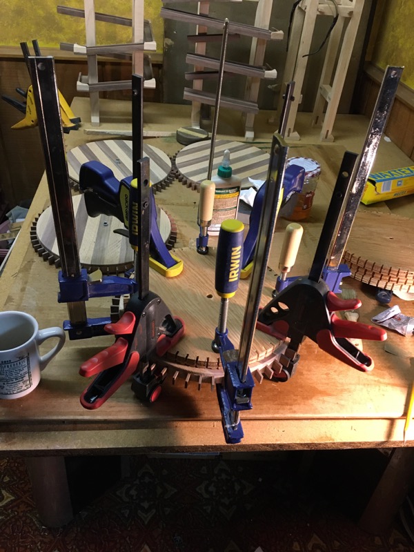
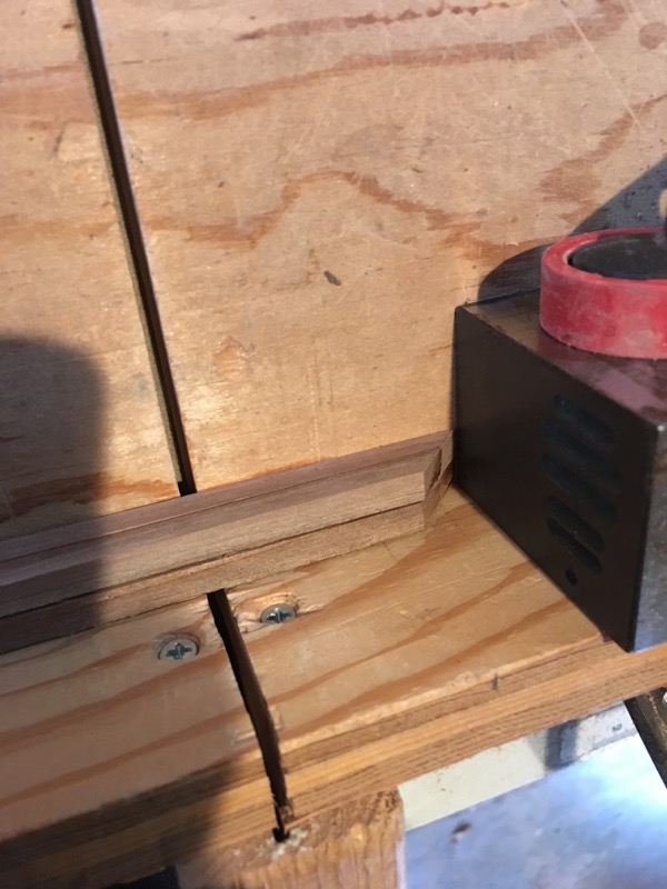
Fixture for gluing ball tracks
All dimensions for these ball tracks were calculated at 80% of the first clock. This includes the measurements for the lengths and widths for all the pieces as well as the thickness of the wood.
I cut and glued it all together (including the making of new jigs and gluing fixtures).
I built this fixture to hold the tracks while gluing. This is necessary in order to keep the sides perfectly square with the bottom. When I just used clamps they tended to squeeze together on top.
The fixture is basically two 'L' shaped strips nested one on top of the other. The top strip is loosely screwed to the bottom strip. The holes for the screws are enlarged and the screws have fender washers and are tightened firmly but not tight, so the strip can slide with the clamps.
Ball Racks- will 80% size reduction work?.
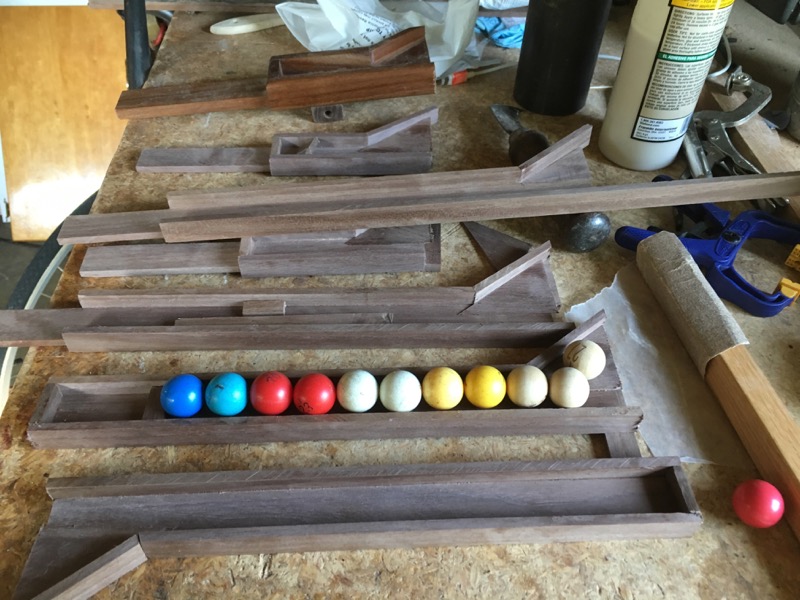
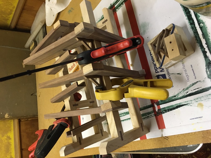
Ball racks for smaller balls
All dimensions for these ball racks were also 80% of the first clock. I cut and glued all the pieces -- this isn't easy to do with these angles.
... then I added the balls. The racks are too long! By about 2 balls. Now what?
I'll have to think about this while I work on the gears....
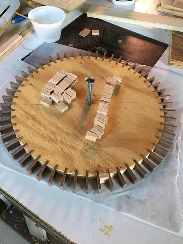
Changes in the way I make the gears.
Clock Gears with teeth and spacers
In the first clock, I made the gears by sequentially gluing teeth and spacers around the circumference of the core disk. I used a printed template as a guide to keep a running track of the spacing so that I'd end up with equally spaced teeth all around the gear. This worked OK. But not great. The resulting gears meshed well over 90% of rotation. It quickly became obvious that this MUST be 100% for the clock to keep accurate time.
Therefore spacing is critical! Anyone who has made gears will say; "Duh".
If you Google "wooden gears", you will find many sites that describe cutting gears out of plywood. There are template generators that will print out patterns. But I prefer the look of walnut teeth and oak spacers set in a plywood core and covered with hardwood facings.
Universal Dividing Head.
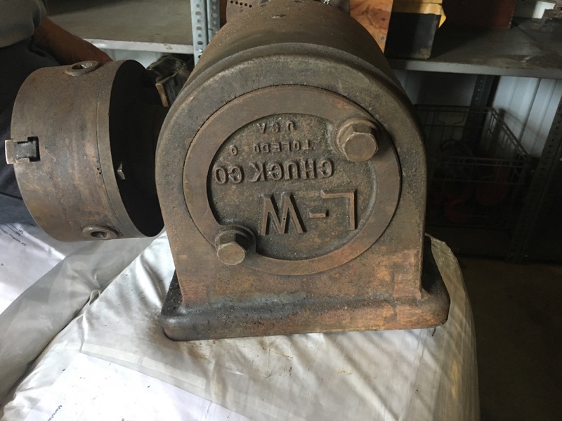
Dividing Head
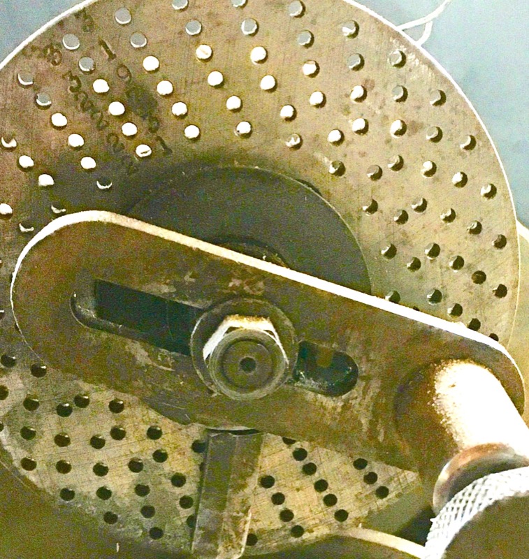
Index wheel
This Dividing Head is designed for making precision gears and is usually attached to a metal milling machine. It allows you to cut precisely spaced gear teeth in a metal disk (or blank). I will use it on wood.
The dividing head has a ratio of 40:1 between the index wheel and the chuck.
I need 54 teeth in the gear so I will turn the indexing wheel 40/54th of a turn for each tooth.
This fraction reduces to 20/27th. The indexing wheel happens to have an orbit with 27 holes so I will select that orbit and count 20 holes between each tooth cut. (here is a calculator on the web if you're lazy)

Wooden Gear Cutting Fixture
Here is the Dividing Head mounted on a frame for cutting gear teeth slots equally spaced on a stack of 4 plywood disks, clamped together and chucked.
(click on picture to enlarge)
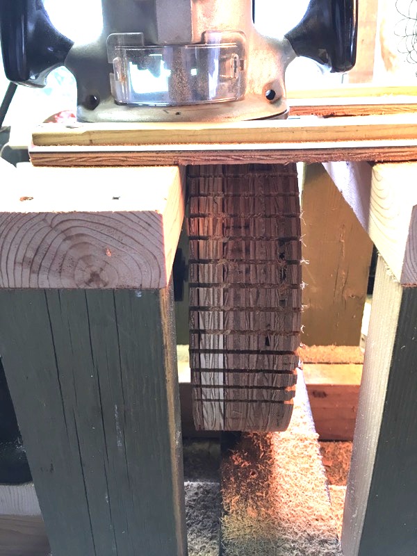
Four gear stack
I stacked 4 disks and clamped them together with a long 3/8" bolt. I chucked this into the Dividing Machine and made passes with a router to cut the grooves for the gear teeth. It took between 10 and 20 minutes to make all the grooves.
The proof of accuracy came if the last cut matched the first one exactly. I ended up repeating this on three sets of disks before I got it right. (third time's the charm).
Now what to do with all those mistakes? Too nice to throw away. Put em on the shelf -- I'll think of something.
(click on picture to enlarge)
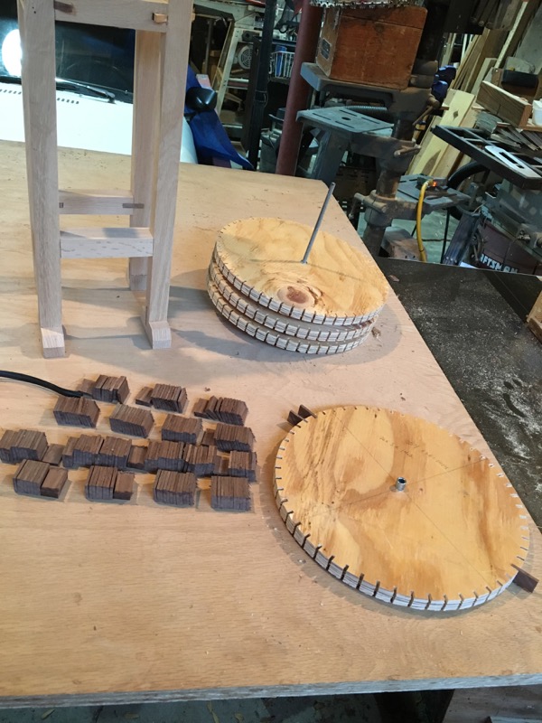
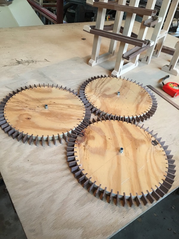
Finished disks
Cut strips of Black Walnut to the thickness of the grooves and a width slightly larger than the thickness of the disks.
Slice off tiles the desired length of the gear teeth (figure in the depth of the groove and the thickness of the spacers to be added between teeth.)
(click on picture to enlarge)
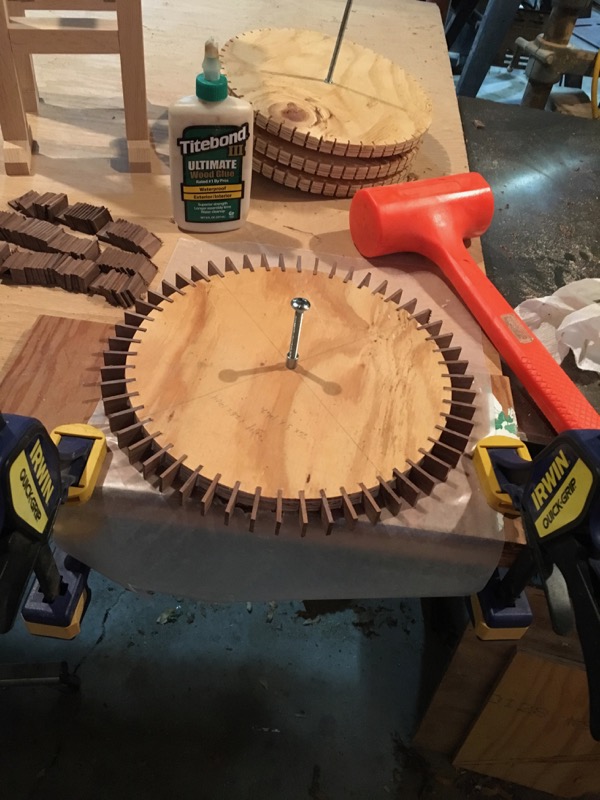
Adding teeth to gear
54 precisely cut Black Walnut gear teeth are glued and then tapped into the grooves of each gear.
One thing I learned on the first clock was to make these teeth with the wood grain aligned radially. Otherwise the tooth can break off.
With these grooves, I could easily just set the teeth and call it good. But I like the look of the oak spacers.
(click on picture to enlarge)
Oak Spacers to gear teeth.
Adding teeth to gear
So again, Cut out spacers and glue in place - one at time.
These spacers are cut 90 degrees from the gear teeth (grain-wise) so the side grain is exposed on the outside of the gear; going across the face of the gear.
(click on picture to enlarge)
Cutting spacers
- cut Red Oak into sheets 5 mm thick.
- cut strips with a bevel edge on two sides at an angle that corresponded to the angle of the teeth. (I'll have to look that up.)
- Stack all these strips on slide -- against an end block -- and slice off the spacers.
(click on picture to enlarge)
Gluing Spacers
I put the glue on the wheel, instead of on the spacers. I was afraid my hand wasn't steady enough to get a spacer full of glue past the ends of the walnut teeth. Since the ends of these teeth will be exposed on the finished wheel, I did not want any glue on them. It would be a nightmare to sand each tooth.
(click on picture to enlarge)
Setting Spacers
Then set each spacer in the slot. I had a short piece of wood that I used to tap each spacer home.
Take care to keep to center the space between the wheel edges with a little bit extending past each side. I will sand all these pieces flush with the faces of the wheel before adding the wheel facings.
(click on picture to enlarge)
Once all the teeth and spacers are placed and glued, use belt sander to level both faces (and sand off the burn shown on these spacers.)
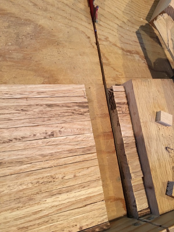
Gear Facings (hub caps)
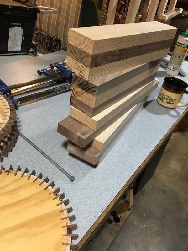
Making Laminate Blocks
Cut out and glue up billets of alternating Red Oak and Black Walnut. After gluing, these cannot exceed 3" on a side since this is all I can cut with my table saw.
I will slice off 5mm on each of these billies and then glue these slices together.
(click on picture to enlarge)
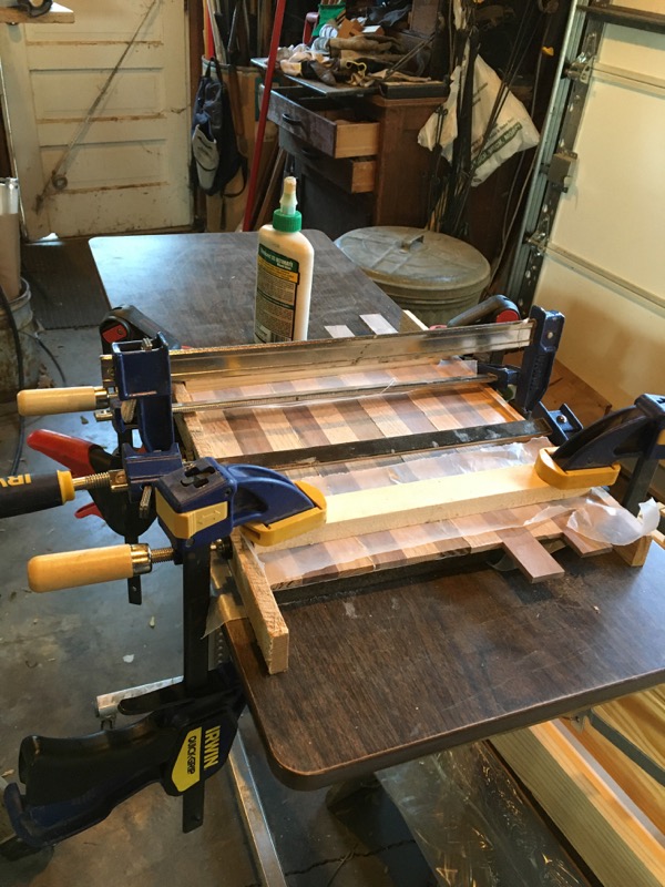
Gluing slices
In gluing these thin slices, side to side, the trick is to keep everything flat while clamping.
(click on picture to enlarge)
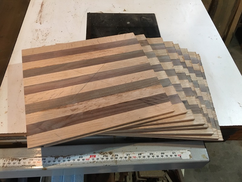
Finished sheets
Finished sheets are ready for making disks.
(click on picture to enlarge)
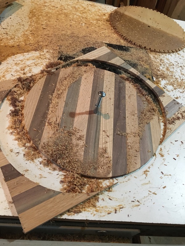
cutting disk
Cut Disk. This took me an awful lot of time -- not to cut the disk -- but to decide how big to cut it. On the first clock, I made these disks just a bit larger than the plywood core of the wheel. This exposed most of the length of the teeth and the spacers between.
This time I decided to bring the disks even with the top of the spacers.
I sanded the edges and put a slight round over on the outside edge.
(click on picture to enlarge)
Glue disk onto wheel
I found a use for those mistakes I made in cutting the gears.
Don't forget to only attach one side -- for now.
(click on picture to enlarge)
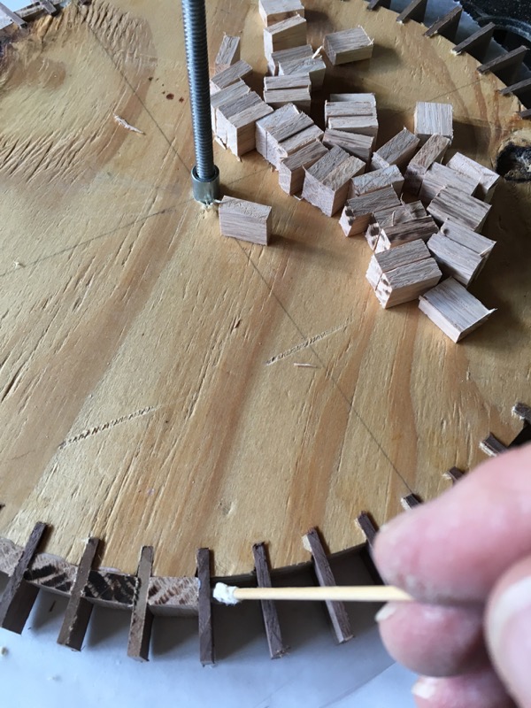
Hole in gear to carry ball.
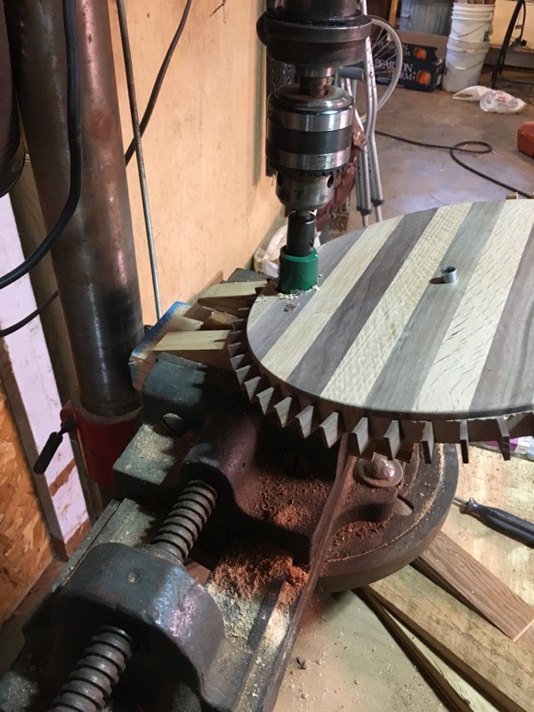
Cutting hole
Cut a hole at 20 degrees completely through the gear face and core. When the other side is glued on to the gear, this will create a cavity to carry the ball.
(click on picture to enlarge)
A big question in my mind was where to cut this hole. I want it as close to the edge as possible in order to make sure it raises the ball high enough. But not so close to the edge that the angle takes it out into the gear teeth on the back side. A little geometry solved this problem.
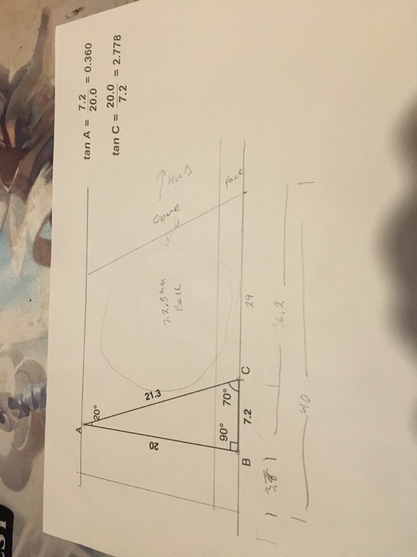
Calculation
I determined that the top of the hole should align with the top of the bottom strip of walnut.
(or 40 mm.)
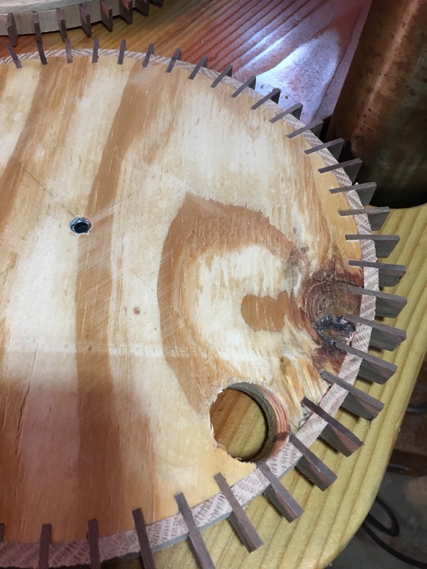
Back side
. . . and here is how it turned out. Now to glue on the second face to close the back of the hole.
Completed Gears
After gluing on the second 'hub cap', the gears are complete and ready for finish.
Note: The center hole is 3/8". There is a 1/4" metal 'bearing' that is cut just long enough to be flush with both faces of the gear.
(click on picture to enlarge)
A note of warning on the axle hole: On the first clock I drilled this hole at 1/4" for the construction phase. When the gears were all assembled I decided to use a metal bushing. It's very difficult to ream out a hole to 3/8", and have it perfectly centered, after the fact.
Now for the clock bases

Clock Bases
I make these out of four strips of lumber. This allows me to do all the cutting on my table saw as the width of any one piece is less than 3".
It also allows me to use a shorter piece for the notch. This way I don't have to saw that out afterwards.
I used different wood species for each clock:
- The one on the right is Red Oak
- The other (L.) is Burr Oak (Grey oak) that was cut and milled in River Falls and originally meant for use as purlins on a barn roofing project.
- The wood never got used for that - the barn was taken down (See Barn Web Page) - so here they are.
The wood is actually quite pretty don't you think? Too nice for purlins.
These are sanded and waiting for a finish to brighten them up.
February 2020: Slow progress on the 'little' clocks.

Small pieces
The clocks are progressing at a snall's pace. It is truely governed by the 90/10 rule (the final 10% of the project takes 90% of the effort).
Here, I'm gluing up the small braces that go under the wide tracks. These are more for looks than function because the glue on the tracks is enough to hold them onto the frames. But the looked so good on the original clock that I had to include them.
But this is fiddle-y work and very time consuming.
OR, I might call it 'attention to detail'. What do you think?
Cutting parts for braces
Just a note here on cutting pieces so that the legs of the brace will be equal length.
I cut bevels in the ends of two pieces of stock at 45°. Then I lined up the long side of one with the short side of the other and cut this to length.
I'm sure you know this trick but I put this here to remind myself.
The picture shows four pieces of stock cut together to make quicker work of this tedious process.
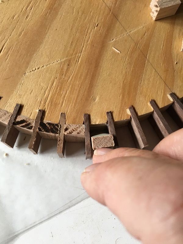
Attaching braces
These braces are tricky to clamp.
The top leg needs to be angled to mate with the sloping ball track.
March 2020: Finally applying finish coat.
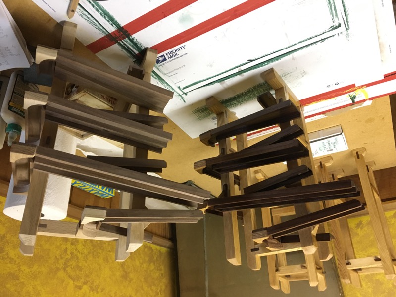
Finishing Clock towers
As we hunker down at home to weater this pandemic, I am pushing ahead to complete these two clocks.
I've waited untill I finished gluing on pieces and now it's time to apply the Polyeurithane finish. You can see the diference in color in this picture -- one finished, the other bare wood. The walnut really darkens.
Click on image to get better look...
Making some adjustments in the ball racks.
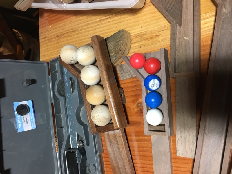
'measuring' ball racks
There was a problem with the scale proportioning that I calculated for these clocks. I cut these ball racks to the same scale that I made the rest of the clock but when I put the actual balls in them it was obvious they were too long. The scale for the clock has been 80$ but, based on ball size ratio, it should have been 75.5%
The correction involved shortening the ball tray on each rack. For some this was as easy as sawing off the end and putting on a new stop. For others it was a delicate task of removing excess length without cutting into the base -- the extension piece at the end.
in the wicture you see the comparison between the full size 1-minute rack and the scaled 1-minute rack to see how the balls should line up at the open end. (I am using extra end pieces to fill in the gap -- this will be trimmed to this length.